
Reactor Vent VOC Treatment Systems for Industrial Process Emissions
Reactor vent VOC treatment systems are often specified after the process design, equipment layout, batch recipe, and utility assumptions have already been fixed. That creates a common retrofit problem: the abatement system is expected to handle variable solvent emissions, pressure-sensitive venting, nitrogen purges, vacuum pump discharge, campaign changes, and maintenance constraints within a vent system that may not have been designed for reliable VOC control.
In a batch plant, the design case is rarely the average exhaust flow. A reactor may vent at a low rate during most of the batch, then produce a short solvent-rich discharge during charging, vacuum stripping, depressurization, or nitrogen purging. That transient event may define the carbon bed size, condenser duty, oxidizer inlet controls, fan capacity, LEL protection, or allowable vent header pressure.
For chemical, pharmaceutical, coatings, food ingredient, and specialty manufacturing plants, reactor vents are not comparable to general room exhaust. They are process-linked emission points. Their behavior changes with solvent vapor pressure, batch temperature, liquid level, condenser performance, vacuum system operation, inerting practice, and operator sequencing.
A reactor vent VOC treatment system should therefore be evaluated from a process design basis, not from a nominal airflow value or annual solvent loss estimate alone. Before issuing a vendor RFQ, the plant should confirm whether the available data represents normal operation, peak solvent events, cleaning conditions, vacuum operation, and credible simultaneous operation cases.
The main engineering questions are practical:
- Which batch step creates the maximum VOC mass rate?
- Can two or more reactors create coincident solvent peaks?
- What backpressure can the reactor, vacuum system, or vent header tolerate?
- Are the VOCs recoverable, destructible, corrosive, water-soluble, or poorly adsorbed?
- Will the selected system create condensate, spent carbon, scrubber blowdown, or acid gas treatment requirements?
- Can production continue if the abatement system is warming up, regenerating, isolated, or under maintenance?
For plant managers, the concern is production availability and lifecycle cost. For EHS managers, it is emissions performance, operating limits, and monitoring reliability. For process engineers, it is the interaction between the reactor, vent header, pressure control, safety logic, utilities, and treatment equipment.
A credible design has to satisfy all three perspectives.
Why Reactor Vent VOC Treatment Is Different from General Exhaust Treatment
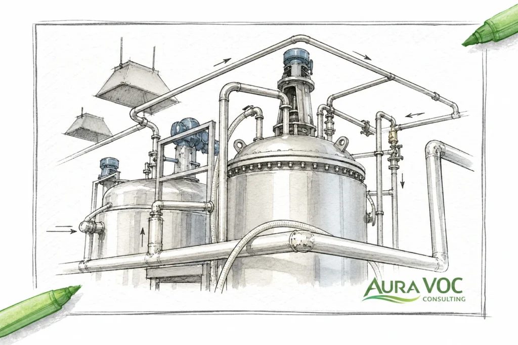
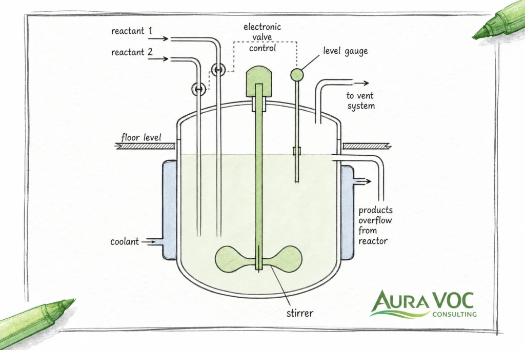
Reactor vent VOC treatment requires a different design approach because the vent stream is directly connected to process operation. General exhaust systems are usually evaluated around ventilation rate, capture efficiency, and steady fan operation. Reactor vents are governed by batch sequencing, solvent behavior, pressure control, vapor-liquid equilibrium, vacuum systems, inerting practices, and safety interlocks.
A general exhaust stream may have a relatively stable flow. A reactor vent may have little or no flow for part of the batch, followed by a concentrated solvent pulse during charging or depressurization. A general exhaust system may tolerate moderate changes in pressure drop. A reactor vent system may have a defined allowable backpressure that affects vessel pressure control, vacuum performance, or purge effectiveness.
This distinction matters during both new system design and retrofit evaluations. Applying a standard VOC abatement package without understanding the reactor operating profile can lead to undersized equipment, unnecessary dilution air, unstable oxidizer operation, premature carbon breakthrough, excessive pressure drop, or solvent condensation in the vent header.
Reactor vents are process-dependent emission sources
A reactor vent is not simply an outlet for contaminated air. It is part of the process system. Its flow and composition depend on what the reactor is doing at a specific point in the batch or production cycle.
During solvent charging, vapor displacement can create a short but concentrated VOC load. During heating, solvent vapor pressure increases and the vent stream may become richer or wetter. During reflux, upstream condensers may remove most of the solvent vapor but still allow residual VOCs to pass forward. During vacuum operation, the discharge from the vacuum pump can introduce solvent vapor, seal fluid mist, oil mist, or non-condensable gases into the treatment system. During nitrogen purging, VOC concentration may fall while total flow increases.
These variations affect every downstream design decision. A carbon bed sized on average solvent mass may break through quickly if it receives repeated high-concentration pulses. A condenser selected without the correct inlet temperature and solvent vapor load may recover less solvent than expected. An RTO may require more supplemental fuel if the average VOC loading is too low, even if the peak loading is high. A scrubber may be inappropriate if the compounds are poorly soluble or if the resulting blowdown creates wastewater treatment problems.
Process dependency also means that campaign changes can alter the treatment duty. In multiproduct plants, a reactor vent system may see different solvents, reaction temperatures, purge rates, and cleaning procedures over time. A design that works for one recipe may be marginal for another if the solvent mix, vapor pressure, or flammability profile changes.
Batch peaks matter more than average emissions
For reactor vent VOC treatment, average emissions data can be misleading. Annualized solvent loss, average VOC concentration, or average airflow may be useful for reporting, but they are not sufficient for equipment design.
Many reactor vent problems occur during short-duration events. Solvent charging may displace a concentrated vapor volume over a few minutes. Depressurization may create a temporary high-flow condition. Vacuum pump discharge may produce a solvent-rich stream during drying or stripping. Nitrogen purging may increase total flow while reducing concentration, changing the operating point of the treatment system.
The treatment system must be evaluated against these transient conditions. The relevant design question is not only “What is the average VOC load?” but also “What is the maximum VOC mass rate, at what flow, for how long, and how often?”
This distinction affects technology selection. Carbon adsorption can be effective for intermittent emissions, but only if bed capacity, mass transfer zone, temperature rise, and breakthrough monitoring are properly addressed. Condensation may be attractive for high-concentration solvent peaks, but residual VOCs may still require polishing. An RTO can destroy mixed solvent vapors, but a highly variable batch load may require dilution control, bypass prevention, purge logic, and a realistic assessment of fuel consumption during low-load periods.
Peak-load evaluation is also important when several reactors feed a common vent header. If two or three units can charge solvent, purge, or depressurize at the same time, the design case may be very different from a single-reactor profile. Plants need to define whether simultaneous events are possible, prohibited by procedure, or controlled by automation.
Reactor vents can affect process operation
The VOC treatment system is downstream of the reactor, but it can still affect upstream operation. Added pressure drop from ductwork, demisters, carbon beds, scrubbers, oxidizers, dampers, and flame arrestors can influence how the reactor vents under normal and abnormal conditions.
For pressure-sensitive operations, the allowable backpressure must be defined before equipment is selected. Excessive resistance can affect nitrogen purge flow, vessel pressure control, solvent charging rates, vacuum pull-down time, or venting performance during controlled depressurization. In some cases, the fan and control system must be designed to maintain stable header pressure while protecting both the reactor and the abatement equipment.
Vacuum systems require particular attention. A vacuum pump discharge may contain solvent vapor, water vapor, oil mist, seal liquid carryover, or condensable material. If this stream is routed directly to carbon adsorption, condensation, or oxidation without adequate knock-out and mist removal, downstream problems can develop quickly. Carbon beds can foul or heat up, condensers can become overloaded, and oxidizer inlet systems can experience liquid carryover risk.
The treatment system can also become a production availability issue. If the VOC abatement unit requires warm-up, purge cycles, regeneration, carbon replacement, condenser defrosting, or scrubber maintenance, the plant needs a clear operating philosophy. Can the reactor operate when the treatment system is offline? Is there an approved standby mode? Are bypasses physically locked, monitored, or prohibited? Are batch steps interlocked with abatement system readiness?
These questions are not secondary. They determine whether the VOC treatment system is an integrated part of production or an unreliable add-on that creates operating restrictions.
Reactor Vent Sources Commonly Connected to VOC Treatment Systems
A reactor vent VOC treatment system rarely receives emissions from the reactor vessel alone. In many plants, the treatment device is connected to a vent header serving multiple process sources. Each source can have a different flow profile, solvent concentration, temperature, moisture content, and pressure behavior.
Understanding these sources is necessary before selecting abatement technology. A system handling only residual condenser vents may have a very different design basis from one handling solvent charging, vacuum pump discharge, nitrogen purges, and cleaning vents through the same header.
Batch and continuous reactors
Batch reactors typically produce variable emissions linked to discrete process steps. Solvent charging, heating, reflux, vacuum, stripping, depressurization, and cleaning can each generate different vent conditions. The timing and intensity of emissions depend on recipe, operating temperature, solvent quantity, agitation, condenser performance, and purge practices.
Continuous reactors can produce more stable vent conditions, but they still require careful review. Feed composition changes, pressure control vents, startup and shutdown conditions, catalyst changes, cleaning cycles, and upset scenarios may create emission cases that differ from normal operation. For continuous processes, the design basis should separate normal steady operation from startup, shutdown, and non-routine venting.
In both cases, the treatment system should be evaluated against realistic operating envelopes rather than a single design point.
Solvent charging and displacement vents
Solvent charging is one of the most important emission sources in reactor vent design. Adding solvent or raw materials to a vessel displaces vapor from the headspace. If the vessel contains residual solvent vapor, is warm, or is being charged at a high rate, the resulting VOC load can be significant even if the event is short.
This type of emission can challenge carbon adsorption and condensation systems because the instantaneous mass loading may be much higher than the batch average. It can also create LEL management issues if the stream is solvent-rich and oxygen is present. For oxidizers, solvent charging events may require careful dilution, flow control, and safety interlocks.
Solvent charging should be treated as a specific design case, not as a minor operating detail.
Vacuum pump discharge streams
Vacuum pump discharge is frequently underestimated in reactor vent VOC assessments. Drying, stripping, distillation, and solvent removal steps can transfer VOCs through the vacuum system rather than through the main reactor vent.
The discharge characteristics depend on the pump type. Oil-sealed pumps may introduce oil mist and solvent-contaminated oil vapor. Liquid ring pumps can generate contaminated seal liquid and humid discharge gas. Dry pumps may discharge hotter vapor streams with less liquid carryover, but they can still require cooling or knock-out protection depending on the process.
Before routing vacuum pump discharge to a VOC treatment system, the design should evaluate solvent load, water vapor, discharge temperature, mist carryover, condensate formation, and pressure fluctuations. In many cases, a knock-out pot, condenser, demister, or separator is needed upstream of the main abatement device.
Vacuum pump discharge can also affect wastewater planning. Liquid ring seal fluid, contaminated condensate, and separator drains may create liquid waste streams that are not visible in a simple air emissions calculation.
Condensers, receivers and reflux systems
Primary condensers and receivers often reduce solvent emissions before the vent reaches the VOC treatment system. However, they should not be assumed to eliminate the treatment requirement. Residual vapor can pass through depending on condenser temperature, solvent vapor pressure, heat-transfer performance, non-condensable gas flow, and fouling condition.
A condenser that performs well during steady reflux may not perform the same way during startup, heat-up, vacuum operation, or high non-condensable flow. Receiver vents can also release VOCs during filling, draining, pressure equalization, or temperature changes.
For treatment system design, condenser performance should be evaluated under actual operating cases. The residual VOC load after condensation may determine whether carbon polishing, oxidation, or a secondary condenser is appropriate.
Nitrogen purge and inerting vents
Nitrogen purge and inerting vents can change both the flow and flammability profile of the vent stream. A nitrogen sweep may reduce oxygen concentration but increase total volumetric flow. It can dilute VOC concentration while maintaining or increasing total VOC mass transfer from the liquid phase, depending on process conditions.
For carbon adsorption, higher purge flow can reduce residence time and increase pressure drop. For condensation, high non-condensable gas flow can reduce recovery efficiency. For oxidizers, nitrogen-rich streams may affect heat balance and require careful oxygen and LEL review.
Inerted systems also require attention to transitions. Oxygen ingress during opening, charging, cleaning, or maintenance may create different flammability conditions than normal inerted operation. The treatment system should be designed around credible operating cases, not only the ideal inerted condition.
Cleaning and solvent wash vents
Cleaning steps can produce VOC emissions that differ from normal production. Solvent washes, rinsing, vessel opening preparation, heated cleaning solutions, and campaign changeovers may introduce different compounds, higher moisture, or intermittent vapor releases.
These emissions are often missed because they are not part of the main reaction step. However, they can affect carbon bed life, condenser load, scrubber blowdown, odor performance, and short-term emission peaks. If cleaning solvents differ from production solvents, adsorption capacity, condensability, corrosion risk, and waste classification may also change.
For multiproduct plants, cleaning and changeover vents should be included in the reactor vent VOC treatment design basis, especially where production campaigns vary throughout the year.
Reactor Vent Characteristics That Drive VOC Treatment Design
A reactor vent VOC treatment system should be designed from the vent profile, not from a generic exhaust assumption. The key variables are not only airflow and VOC concentration, but how those values change during the batch, how they interact with solvent chemistry, and what constraints exist upstream of the treatment equipment.
For existing plants, the required information is often spread across process data sheets, batch records, solvent inventories, condenser logs, vacuum pump data, stack tests, maintenance records, and operator experience. A reliable design basis usually requires reconciling these sources rather than relying on a single emissions measurement.
The following design variables should be treated as part of the same system evaluation:
| Design variable | Why it matters | Systems affected |
|---|---|---|
| Peak VOC mass rate | Defines the real treatment duty during short events | RTO, carbon adsorption, condensation |
| Peak-to-average flow ratio | Affects turndown, residence time, fan sizing, and pressure drop | All systems |
| Solvent composition | Determines adsorbability, condensability, heat release, corrosion, and wastewater impact | Carbon, condenser, oxidizer, scrubber |
| Moisture and condensables | Can reduce adsorption capacity, foul equipment, increase corrosion, or create liquid carryover | Carbon, fan, demister, oxidizer |
| Oxygen and nitrogen content | Affects LEL control, inerting assumptions, dilution demand, and oxidation safety | Oxidizer, RTO, carbon, controls |
| Allowable backpressure | Determines whether the abatement system can be connected without affecting the process | Vent header, vacuum system, fan, treatment unit |
| Utility availability | Can limit feasible technology options | RTO, condenser, scrubber, carbon regeneration |
| Secondary waste routes | Determines handling of condensate, blowdown, spent carbon, or regeneration streams | Condenser, scrubber, carbon, oxidation with acid gas control |
Vent flow range and peak-to-average ratio
The flow range defines the hydraulic duty of the system, but the peak-to-average ratio defines much of the operating risk. Reactor vents may operate at very low flow during holding or reaction phases, then experience much higher flow during nitrogen purging, depressurization, vacuum operation, or simultaneous charging events.
A high peak-to-average ratio affects fan sizing, duct velocity, residence time, pressure drop, oxidizer turndown, carbon bed contact time, condenser performance, and monitoring response. A system sized only for average flow may fail during short high-flow events. A system sized only for the maximum case may operate inefficiently for most of the batch.
For batch operations, the design should define maximum instantaneous flow, normal flow, minimum flow, event duration, and event frequency. These values should be linked to specific batch steps, not listed as isolated data points.
VOC concentration and mass loading
VOC concentration alone is not enough. The treatment system must also be evaluated against VOC mass loading.
A short, concentrated solvent vapor pulse can be more important than a long low-concentration emission period. For carbon adsorption, mass loading affects bed life, breakthrough time, heat release, and changeout frequency. For condensation, it affects refrigeration duty and recovered liquid rate. For oxidizers, it affects heat release, dilution requirements, and fuel balance. For scrubbers, it affects absorption duty, chemical demand, and blowdown load.
Peak VOC mass rate should be estimated for each relevant batch step and checked against solvent balance data where possible. If measured stack data does not capture charging, stripping, vacuum operation, or cleaning, it may understate the real design duty.
Solvent composition and vapor pressure
Solvent identity is a primary design variable. Two vent streams with the same total VOC concentration can behave differently if the solvent composition changes.
High-vapor-pressure solvents may pass through condensers more readily and create higher emission rates during warm operations. Water-soluble compounds may be partially treated in scrubbers, but may also increase wastewater COD. Chlorinated or sulfur-containing compounds may create corrosive byproducts if oxidized and may require downstream scrubbing or special materials of construction. Ketones, aromatics, alcohols, esters, and mixed solvent systems may have different adsorption behavior on activated carbon.
Multiproduct plants require particular attention. If campaigns change throughout the year, the design should not be based only on the most common solvent. Low-volume campaigns can still create the limiting design case if they involve more volatile, corrosive, poorly adsorbed, or higher-heating-value compounds.
Temperature, moisture and condensables
Temperature and moisture influence treatment performance and equipment reliability. Warm vent streams can carry higher solvent vapor loads. Cooling in the vent header can cause solvent or water condensation. Moisture can reduce carbon adsorption capacity, increase corrosion risk, affect catalyst life, and create visible plume or condensate handling issues.
Condensables are a frequent cause of operating problems. Liquid accumulation in low points can increase pressure drop, create corrosion, produce slugs into downstream equipment, and contaminate carbon beds. For oxidizers, liquid carryover can create safety and temperature-control concerns. For carbon adsorption, liquid solvent entering the bed can increase fire risk and reduce effective bed capacity.
A practical design should consider insulation, heat tracing, drainage, knock-out pots, demisters, and materials of construction where condensate formation is credible.
Oxygen, nitrogen and LEL constraints
LEL management should be based on credible peak solvent concentration and oxygen conditions, not only on normal inerted operation. A nitrogen-blanketed reactor may be oxygen-lean during reaction, but oxygen conditions can change during charging, vessel opening preparation, cleaning, maintenance, or startup.
Dilution air can reduce solvent concentration, but it also increases total flow, fan power, duct size, oxidizer size, and sometimes fuel use. In an RTO, excessive dilution can turn a solvent-rich intermittent stream into a larger low-heating-value stream that costs more to treat. In a carbon system, high solvent loading in the presence of oxygen can increase bed temperature concerns.
Sensor location is also important. LEL measurements should represent the mixed stream that reaches the treatment equipment, not a stagnant branch, unmixed header zone, or location downstream of dilution where the peak has already been masked. Batch control logic may also need to prevent solvent charging, vacuum operation, or purge steps unless the abatement system is confirmed ready.
LEL protection should be treated as part of the process control philosophy, not as an instrument added after technology selection.
Pressure constraints and allowable backpressure
Allowable backpressure is often the limiting design constraint for reactor vent treatment. Added resistance from ductwork, filters, demisters, carbon beds, scrubbers, valves, flame arrestors, and stacks can affect reactor operation.
Pressure constraints are especially important where reactors operate under vacuum, slight positive pressure, nitrogen blanketing, or controlled depressurization. If pressure drop is underestimated, operators may see longer vacuum pull-down times, reduced purge effectiveness, unstable vessel pressure control, or restricted charging rates.
The design should include a pressure drop budget across the complete system, from the reactor nozzle or vent header to the stack discharge. For retrofits, this review should include existing ductwork, bends, low points, dampers, and any equipment already installed upstream of the proposed treatment unit.
Process Data Required Before Selecting a Reactor Vent VOC Treatment System
Technology selection should not begin with equipment preference. It should begin with process data. Without a defensible design basis, the comparison between RTO, carbon adsorption, condensation, scrubbing, and hybrid systems becomes speculative. EPA guidance on reactor and distillation process VOC emissions can be used as a technical reference when defining process vent control requirements.
The most useful data is not always a single stack test. For reactor vents, plant operating records, batch sheets, solvent charging logs, condenser temperatures, vacuum pump data, and production schedules often provide a clearer picture of the true emission profile.
Batch-step emission profile
A batch-step emission profile maps expected vent conditions across the production cycle. It should identify when VOC emissions occur, how long each event lasts, and what conditions exist during each step.
Typical steps include solvent charging, raw material addition, heating, reaction, reflux, distillation, vacuum stripping, nitrogen purge, depressurization, transfer, cleaning, and vessel preparation. Each step can have different flow, temperature, solvent composition, and oxygen content.
This profile is useful because it separates low-load operating periods from short high-load events. It also allows engineers to evaluate whether treatment equipment should be sized for peak flow, buffered before treatment, condensed upstream, or controlled through batch sequencing.
Solvent and process chemistry data
The solvent list should include all normal production solvents, cleaning solvents, campaign-specific solvents, and credible byproducts that may enter the vent system. For each compound, useful data includes vapor pressure, boiling point, flammability limits, water solubility, adsorption behavior, corrosive combustion products, and compatibility with system materials.
This information directly affects technology selection. Condensation depends heavily on vapor pressure and cooling temperature. Carbon adsorption depends on molecular properties, humidity, concentration, and bed conditions. Oxidation requires review of heat release, corrosion potential, acid gas formation, and safety controls. Scrubbing depends on solubility, reaction chemistry, liquid handling, and wastewater treatment capacity.
Where solvent mixtures are variable, the design should identify both typical and limiting cases.
Simultaneous reactor operation cases
In plants with multiple reactors connected to one treatment system, simultaneous operation is a critical design assumption. If several reactors can charge solvent, purge, or depressurize at the same time, the combined peak flow and VOC mass rate may be much higher than the single-reactor case.
The assessment should define which coincident events are physically possible, which are allowed by operating procedure, and which are prevented by automation. If simultaneous peaks are prevented only by operator practice, that assumption should be treated carefully. A control-based restriction may require interlocks, batch scheduling rules, or administrative limits.
This issue is particularly important for centralized treatment systems. A common vent header can reduce equipment duplication, but it can also introduce pressure interactions, solvent compatibility concerns, and shared downtime risk.
Existing vent header and equipment data
For retrofits, the existing vent system often determines what is practical. Duct routing, header size, material compatibility, slope, low points, isolation valves, condensate drains, and available tie-in locations can all affect the final design.
Upstream equipment should also be reviewed. Condensers, receivers, vacuum pumps, knock-out pots, demisters, flame arrestors, fans, and existing scrubbers may already influence the vent stream before it reaches the new treatment device. A poorly draining header or undersized demister can make a downstream carbon bed or oxidizer unreliable regardless of how well that equipment is specified.
For accurate evaluation, drawings should be checked against the installed system. Field verification is often necessary in older plants where vent headers have been modified over time.
Utility and site constraints
VOC treatment equipment requires utilities, space, access, and waste handling capacity. These constraints should be identified before selecting technology.
RTOs and thermal oxidizers may require natural gas, electrical power, compressed air, and adequate stack location. Condensation systems may require chilled water, cooling water, refrigeration power, defrost capability, and solvent recovery tanks. Carbon systems require space for vessels, safe access for carbon replacement, fire protection considerations, and spent carbon handling. Scrubbers require recirculation pumps, chemical dosing, water supply, blowdown routing, and wastewater treatment capacity.
A technically suitable abatement technology may still be impractical if the site lacks the required utilities, footprint, access, or wastewater capacity. An RTO may be viable on paper, for example, but unavailable gas capacity, long duct routing, limited stack location, or warm-up constraints can make it difficult to operate in an existing batch plant.
VOC Treatment Technologies for Reactor Vents: Where Each Option Fits
Reactor vent treatment technologies should be screened against actual batch behavior, not only against nominal airflow. The correct comparison is not simply RTO versus carbon versus condensation. The practical question is which configuration can handle the peak solvent load, low-load periods, pressure constraints, LEL envelope, secondary waste, and maintenance requirements of the plant. The European Commission BREF for common waste gas treatment in the chemical sector provides useful BAT context for comparing waste gas treatment techniques.
Many reactor vent applications require staged treatment. A condenser may reduce peak solvent load before carbon adsorption. A knock-out pot and demister may protect an oxidizer. A scrubber may be required after oxidation of halogenated compounds. A buffer volume may reduce the severity of short peak events before a thermal system.
Regenerative thermal oxidizers for mixed solvent destruction
Regenerative thermal oxidizers are typically considered where the objective is VOC destruction and solvent recovery is not practical. They can be suitable for mixed solvent vents, centralized process vent headers, and multiproduct plants where solvent composition changes by campaign.
For reactor vents, the main design questions are:
- What is the lowest sustained VOC load?
- How long does the unit remain hot between emission events?
- Is dilution air required during charging or depressurization?
- Are chlorinated, fluorinated, sulfur-containing, or corrosive compounds present?
- Can the plant tolerate warm-up, purge, and standby fuel demand?
- What pressure drop can the upstream vent system accept?
Batch vents may create a difficult RTO operating profile: short solvent-rich peaks followed by long low-load periods. During low-load operation, supplemental fuel may be required to maintain combustion chamber temperature. During high-load events, dilution or flow control may be required to remain within safe inlet limits. If dilution air is excessive, the plant may pay to heat large volumes of air that were added only for safety control.
High RTO fuel consumption should not be evaluated only as an equipment issue. It may result from the production schedule, oversized design flow, poor heat recovery, leaking valves, fouled ceramic media, excessive dilution, or long idle periods between batches.
Catalytic and direct-fired oxidizers for selected process vents
Catalytic oxidizers and direct-fired oxidizers may be appropriate for selected reactor vent applications, but they require careful review of solvent composition and operating stability.
Catalytic systems can reduce operating temperature compared with thermal oxidation, but catalyst poisoning, fouling, halogenated compounds, sulfur compounds, silicones, and particulates can limit suitability. Direct-fired oxidizers may handle certain streams well but can have higher fuel demand and may be less attractive for highly variable batch vents unless the duty is well defined.
For either option, inlet concentration control, purge sequences, flame safety, residence time, and materials of construction should be reviewed against the actual vent profile.
Activated carbon adsorption for solvent vapor control
Activated carbon adsorption can be appropriate for lower to moderate flow reactor vents, intermittent solvent emissions, and polishing after condensation. It is often attractive where the compounds adsorb well and the plant can manage media replacement or regeneration.
The screening questions should include:
- What is the expected bed life during the worst-case campaign?
- Is the gas stream dry enough for reliable adsorption?
- Are ketones, reactive compounds, or high heat-of-adsorption solvents present?
- Can high-concentration slugs enter the bed?
- Is bed temperature monitoring required?
- How will breakthrough be detected before outlet VOC becomes unacceptable?
- Can carbon be changed safely within the available maintenance window?
Carbon systems are often misapplied when only average VOC loading is considered. A bed that appears adequate on annualized mass may break through quickly if it receives repeated concentrated solvent pulses. Moisture can reduce working capacity. Poor flow distribution can create channeling. Liquid solvent or mist carryover can foul the bed and increase fire risk.
Differential pressure, bed temperature, inlet solvent loading, and carbon replacement history should be reviewed together. A rising pressure drop may indicate mist, condensate, particulate, or polymerizable material entering the bed rather than normal carbon aging.
Condensation and cryogenic condensation for solvent recovery
Condensation is most practical when the vent stream contains solvent at sufficient concentration and the recovered liquid has reuse, recovery, or disposal value. It can also reduce the load on downstream carbon adsorption or oxidation.
The main screening questions are:
- What condenser outlet temperature is required for meaningful VOC reduction?
- How much non-condensable gas is present?
- Will the recovered liquid be a reusable solvent, mixed solvent waste, or solvent-water condensate?
- Is freezing, fouling, or hydrate formation credible?
- What residual VOC concentration remains after condensation?
- Is downstream polishing still required?
High nitrogen purge rates or vacuum pump non-condensables can reduce condensation effectiveness because the solvent vapor is carried in a larger gas volume. Mixed solvent systems may produce recovered liquid that is not suitable for direct reuse. Cleaning solvents, water vapor, and reaction residues can also change recovered liquid quality.
Condenser performance should be checked against actual inlet temperature, solvent vapor pressure, cooling utility temperature, fouling condition, and drainage arrangement. A condenser that performs well during reflux may not perform the same way during vacuum stripping or high non-condensable flow.
Wet scrubbers for soluble VOCs or acid gas control
Wet scrubbers are not universal VOC treatment devices, but they can be useful where compounds are water-soluble, chemically reactive, or where acid gas control is required downstream of oxidation.
For reactor vents, scrubber evaluation should include solubility, liquid-to-gas ratio, pH control, chemical consumption, mist eliminator performance, pressure drop, and wastewater load. A scrubber that transfers VOCs from air to water does not eliminate the contaminant; it creates a liquid-phase treatment or disposal requirement.
Scrubbers may also be used as part of a hybrid system, particularly when oxidizing halogenated or sulfur-containing VOCs produces acid gases requiring downstream control.
Hybrid VOC treatment systems for batch reactor vents
Hybrid systems are common where one technology cannot handle all operating cases efficiently. A condenser may recover high-concentration solvent peaks before a carbon bed. A knock-out pot and demister may protect an oxidizer. A scrubber may treat acid gases after oxidation. A buffer tank may smooth intermittent emissions before an RTO.
Hybrid systems can improve reliability, but they add controls, pressure drop, maintenance points, and interface risks. Each stage should have a defined purpose. Adding equipment without a clear duty can increase complexity without solving the limiting design problem.
Engineering Tradeoffs in Reactor Vent VOC System Design
Engineering tradeoffs should be made visible before equipment is specified. Reactor vent VOC treatment often involves competing objectives: low pressure drop versus treatment performance, solvent recovery versus destruction, lower capital cost versus higher utility demand, and high safety margin versus efficient operation.
These tradeoffs are not theoretical. They determine how the system behaves during normal production, campaign changes, maintenance, and abnormal operation.
Solvent recovery versus VOC destruction
Solvent recovery is attractive when the vent stream contains recoverable solvent at sufficient concentration and the recovered liquid can be reused or managed economically. Condensation and adsorption-based recovery may reduce downstream load, but recovered solvent quality, water contamination, mixed-solvent composition, and storage requirements must be assessed.
VOC destruction by oxidation may be more practical for variable or contaminated solvent mixtures, but it can increase fuel use and may create acid gas treatment requirements for halogenated or sulfur-containing compounds.
The decision should be based on more than solvent value. Recovery can create solvent-water condensate, mixed solvent waste, or off-spec material. Destruction can create fuel demand, air dilution requirements, and secondary scrubbing needs. The better option depends on the full operating and waste-handling picture.
Peak-load sizing versus normal operating efficiency
Sizing only for average flow and concentration can miss short-duration solvent peaks. Sizing only for the maximum credible case can create oversized equipment that operates inefficiently during most of the batch.
The design should define whether peak events are treated directly, buffered, condensed upstream, limited by batch sequencing, or managed through control logic. For example, a high-concentration charging event may be better handled by upstream condensation or controlled charging rate than by oversizing the entire downstream system.
This tradeoff is especially important for RTO fuel use, carbon bed sizing, condenser duty, and fan selection.
Pressure drop versus reactor performance
Pressure drop is not only a fan-sizing issue. It can affect reactor pressure control, vacuum pull-down time, nitrogen purge rate, and controlled depressurization.
Carbon beds, scrubbers, demisters, flame arrestors, oxidizers, dampers, and ductwork should be included in a full pressure drop budget. For retrofits, allowable backpressure should be verified before equipment selection. If operators already report slow vacuum response or unstable venting, adding treatment equipment without correcting the pressure limitation can worsen the problem.
Centralized versus point-source treatment
A centralized VOC treatment system can reduce equipment duplication and simplify stack monitoring, but it may create shared downtime risk, pressure interactions, solvent compatibility issues, and more complex LEL management.
Point-source systems can improve source control and reduce header complexity, but they increase equipment count, maintenance points, utility connections, and inspection requirements.
For multiproduct plants, the decision should consider not only installed cost but also batch scheduling, isolation requirements, simultaneous operation cases, and how maintenance on one treatment unit affects production.
CAPEX versus OPEX
Capital cost should not be evaluated separately from operating cost. RTOs may have significant fuel and fan power demand. Carbon systems require media replacement or regeneration. Condensers require refrigeration or chilled utilities. Scrubbers create chemical and wastewater costs.
A lower initial equipment cost can become expensive if it increases downtime, waste handling, fuel consumption, maintenance frequency, or operator intervention. Conversely, a higher capital system may be justified if it reduces solvent loss, avoids frequent media replacement, or improves production availability.
Emission control reliability versus secondary waste generation
Some systems shift the control burden from air to liquid or solid waste. Condensers generate solvent-water condensate. Scrubbers generate blowdown. Carbon systems generate spent media or regeneration condensate. Oxidation of certain compounds may require downstream acid gas scrubbing.
These secondary streams should be part of the technology comparison. A VOC control system that performs well on air emissions may still create a plant constraint if the wastewater treatment system, waste storage area, or maintenance team cannot handle the secondary load.
Operational Constraints That Affect Reactor Vent VOC Treatment
A reactor vent VOC treatment system must fit the way the plant actually operates. Batch timing, cleaning windows, startup procedures, operator sequencing, and equipment availability can determine whether a technically correct design is practical in daily use.
Startup, shutdown and standby modes
Oxidizers may require warm-up and purge sequences before accepting VOCs. Condensers may require pre-cooling. Carbon systems may need bed isolation or standby procedures. Scrubbers may require recirculation flow, pH control, chemical dosing, and mist eliminator readiness.
These operating modes should match the production schedule, especially where batch steps cannot wait for abatement equipment readiness. If the treatment system requires a long warm-up period, the plant needs to define whether solvent charging is delayed, batches are grouped, or the system remains in hot standby.
Production scheduling and treatment system availability
If the VOC treatment system is unavailable, the plant needs a defined operating position. Some sites may stop solvent charging or suspend specific batch steps. Others may have approved backup treatment or temporary controls. Undefined bypass practices create operational and compliance risk.
Production scheduling can also affect operating cost. Spreading short VOC-generating events across a long shift may keep an RTO hot for many idle hours. Grouping compatible batch steps may reduce standby fuel use, but only if it does not create coincident peak loads or header pressure issues.
Batch recipe and campaign changes
A change in solvent, batch size, temperature, purge rate, or cleaning procedure can change the vent duty. Multiproduct plants should review whether the VOC treatment design remains valid when campaigns change, especially when introducing more volatile, chlorinated, sulfur-containing, or poorly adsorbed compounds.
Campaign changes can also affect maintenance. A carbon bed that performs acceptably on one solvent may break through early on another. A condenser selected for one vapor pressure range may underperform on a more volatile solvent. A scrubber may generate a different blowdown composition after a cleaning solvent change.
Control system integration
Reliable operation depends on more than equipment sizing. Batch-step signals, fan speed, damper position, LEL alarms, oxygen monitoring, temperature limits, pressure control, and interlocks must work together.
Poor sequencing can create avoidable trips, high fuel use, or untreated peak emissions. For example, a dilution damper that responds too slowly during solvent charging can trigger LEL alarms. A fan control setpoint that does not account for simultaneous reactor operation can create header pressure instability. A condenser that is not pre-cooled before vacuum stripping may overload downstream treatment.
Separation of normal vents from relief events
Normal reactor vents should not be confused with emergency relief design. Pressure relief devices, rupture discs, or emergency venting scenarios may require separate process safety evaluation.
A VOC treatment system designed for normal process vents is not automatically suitable for relief-device discharge. Emergency relief streams may involve different flow rates, compositions, temperatures, two-phase flow, or safety requirements. Normal vent treatment and emergency relief management should be evaluated as separate design cases unless a process safety review supports a combined approach.
Maintenance Considerations for Reactor Vent VOC Treatment Systems
Maintenance requirements should be considered during technology selection. A system that is difficult to inspect, clean, regenerate, or isolate may create reliability problems even if it is technically suitable on paper.
Carbon adsorption maintenance
Carbon systems require breakthrough monitoring, pressure drop checks, temperature surveillance where applicable, and planned media replacement. Early breakthrough often indicates underestimated solvent load, moisture interference, high-concentration slugs, or poor regeneration performance.
Maintenance access is important. Carbon changeout requires safe isolation, handling procedures, lifting access, and waste classification. For higher-risk solvent services, bed temperature monitoring and fire prevention measures may be required.
Differential pressure trends are also useful. A rising pressure drop may indicate mist carryover, liquid solvent entry, particulate loading, or polymerizable material rather than normal carbon saturation.
RTO maintenance
RTO reliability depends on burner condition, valve sealing, ceramic media condition, fan performance, temperature balance, and pressure drop. Fouled media or leaking valves can reduce heat recovery and increase fuel use.
For reactor vent applications, maintenance records should be compared with production schedule and solvent campaigns. Changes in fuel consumption, pressure drop, destruction performance, or operating temperature can indicate media fouling, valve leakage, poor dilution control, or changes in inlet VOC load.
Condenser maintenance
Condensers require attention to fouling, icing, drainage, refrigerant performance, and solvent recovery tank management. Reduced heat transfer can increase residual VOC loading to downstream equipment.
Operators should track condenser outlet temperature during the relevant batch step, not only during steady operation. A condenser that reaches the required temperature after the peak has passed may still allow a high VOC load to reach carbon or oxidation equipment.
Drainage is also important. Poorly drained condensers, receivers, or knock-out pots can cause liquid carryover, corrosion, and inconsistent solvent recovery.
Scrubber maintenance
Scrubbers require control of pH, chemical dosing, recirculation flow, nozzle condition, packing condition, mist eliminator pressure drop, and blowdown quality. A scrubber that is not maintained becomes both a pressure drop source and a wastewater problem.
For VOC applications, scrubber performance should be connected to solubility and chemistry. If the compounds are only weakly soluble, increasing recirculation may not solve the treatment problem. If acid gas control is the duty, pH and chemical availability become critical operating parameters.
Instrumentation maintenance
LEL sensors, oxygen analyzers, VOC monitors, pressure transmitters, temperature probes, flow meters, and safety interlocks require calibration and functional checks. Instrument drift can lead to false security or unnecessary shutdowns.
For batch systems, instrument location and response time matter. A sensor that is reliable during steady flow may not capture short solvent peaks if the sample location, sample transport, or analyzer response is poorly matched to the process event.
Troubleshooting Common Reactor Vent VOC Treatment Problems
Troubleshooting should start with the batch step where the problem occurs. Many reactor vent VOC issues are intermittent, so daily averages or periodic readings may hide the actual cause. Alarm history, differential pressure trends, solvent charging records, condenser outlet temperatures, vacuum pump operation, and carbon changeout history are often more useful than a single emissions snapshot.
Outlet VOC concentration remains above target
High outlet VOC can result from underestimated peak loading, bypass leakage, poor capture, carbon breakthrough, inadequate condensation, unstable oxidizer operation, or untreated branches tied into the vent header.
The first checks should be practical:
- identify the batch step when the high reading occurs
- compare the event with solvent charging, vacuum operation, purge, or cleaning
- check whether all vent sources are routed as assumed
- review condenser outlet temperature during the event
- inspect bypass dampers or isolation valves
- compare carbon changeout history with production changes
- review RTO temperature, valve position, and inlet concentration trends
If the problem occurs only during certain recipes, the limiting factor may be solvent vapor pressure, different cleaning solvents, poorer carbon adsorption, or a higher peak mass rate than the original design assumed.
Carbon beds break through faster than expected
Early breakthrough usually indicates that the bed is receiving more VOC mass, more moisture, poorer-adsorbing compounds, or higher peak concentrations than expected.
Common causes include:
- solvent charging peaks not included in the design basis
- moisture reducing carbon working capacity
- poor flow distribution through the bed
- high-concentration slugs during vacuum or depressurization
- liquid solvent or mist carryover
- campaign change to a more volatile or poorly adsorbed compound
- regeneration not restoring expected working capacity
The investigation should include inlet and outlet VOC trends, differential pressure, bed temperature, moisture content, solvent composition, and actual batch timing. If differential pressure increases quickly, inspect for mist, condensate, particulate, or fouling rather than assuming normal carbon exhaustion.
RTO fuel consumption is higher than expected
High RTO fuel use is common when batch VOC loading is intermittent. The system may remain at temperature while waiting for short emission events, then operate at low VOC loading for long periods.
Likely causes include:
- low average VOC heating value
- long idle or standby periods
- excessive dilution air
- oversized design airflow
- degraded heat recovery from fouled media
- leaking valves or poor sealing
- cold purge requirements
- production schedule that spreads emissions across long periods
Review natural gas use against production schedule, not only against operating hours. In some plants, batch grouping, upstream condensation, improved dilution control, or revised standby strategy can reduce fuel consumption without changing the primary abatement technology.
Excessive pressure drop affects venting or vacuum performance
If operators report slower vacuum pull-down, unstable vessel pressure, reduced purge flow, or slower depressurization after a VOC abatement retrofit, pressure drop should be investigated across the full system.
Likely causes include:
- fouled carbon beds
- plugged demisters or flame arrestors
- solvent accumulation in low points
- undersized ductwork
- scrubber packing fouling
- closed or partially closed dampers
- fan control setpoint problems
- added equipment not included in the original pressure drop budget
Differential pressure should be measured by section, not only across the final treatment unit. A small pressure loss across several components can create a significant total restriction at the reactor.
Frequent LEL alarms or safety shutdowns occur
Frequent LEL alarms often indicate that the operating envelope is not aligned with the batch sequence. The alarm may occur during solvent charging, vacuum stripping, depressurization, or purge transitions rather than during steady reaction.
Likely causes include:
- solvent peaks not diluted as assumed
- oxygen variation during non-routine steps
- poor mixing before the sensor location
- sensor placement that sees localized peaks
- dilution damper response too slow for short events
- recipe changes not reflected in alarm logic
- simultaneous reactor events through a common header
The troubleshooting review should compare alarm timestamps with batch records. If alarms occur repeatedly at the same step, the issue is usually process-sequence related rather than random instrument behavior.
Solvent condenses in vent headers or downstream equipment
Solvent condensation in vent headers can create pressure drop, corrosion, odor events, inconsistent emissions performance, and liquid carryover into downstream treatment equipment.
Common causes include cold duct surfaces, poor slope, low points, missing drains, insufficient insulation, high solvent vapor load, poor knock-out design, or inadequate heat tracing. Condensation may also increase after production changes if a more volatile or higher-volume solvent is introduced.
Inspection should focus on low points, drains, knock-out pots, demisters, and any section where the gas cools below its dew point. Liquid accumulation upstream of carbon beds, fans, or oxidizers should be treated as a reliability and safety concern, not only as a housekeeping issue.
Wastewater and Secondary Waste Implications
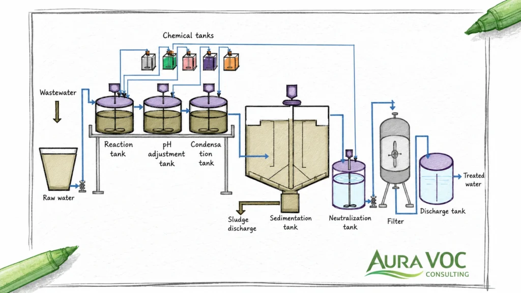
VOC treatment can create liquid or solid waste streams that affect plant operations. These streams should be identified during technology selection, not after commissioning.
Solvent-water condensate from condensation systems
Condensate may contain mixed solvents, water, reaction residues, or cleaning compounds. Reuse depends on purity, phase separation, and contamination. If the condensate cannot be reused, disposal or wastewater treatment capacity must be evaluated.
In multiproduct plants, condensate quality may change by campaign. A recovery system that works for one solvent may produce off-spec or mixed waste during another.
Scrubber blowdown from VOC or acid gas control
Scrubber blowdown may contain dissolved VOCs, salts, acids, alkalis, and elevated COD. This load must be compatible with the site wastewater treatment system.
If the scrubber is used after oxidation of halogenated or sulfur-containing compounds, blowdown composition may be driven by acid gas neutralization rather than VOC solubility alone. Chemical consumption, corrosion, and disposal cost should be included in the evaluation.
Steam-regenerated carbon condensate
Regenerated carbon systems can produce solvent-water mixtures that require separation, recovery, or disposal. This stream should be included in operating cost estimates.
The quality of regeneration condensate depends on the solvent mix, steam rate, regeneration efficiency, and downstream separation equipment. Poor separation can turn a recovery option into a wastewater load.
Spent activated carbon handling
Spent carbon replacement frequency affects maintenance planning and waste cost. Waste classification depends on adsorbed compounds and site-specific handling requirements.
Changeout logistics should be considered before selecting carbon adsorption. Access, isolation, lifting, worker exposure, odor control, and waste documentation can affect whether the system is practical for routine operation.
Acid gas scrubbing after oxidation of halogenated or sulfur-containing VOCs
Oxidation of certain compounds can generate acid gases. Downstream scrubbing may be required, adding chemical consumption, blowdown, corrosion considerations, and wastewater load.
This issue should be reviewed before selecting oxidation for streams containing chlorinated, fluorinated, brominated, sulfur-containing, or other compounds that can form corrosive products during destruction.
Retrofit Considerations for Existing Chemical and Pharmaceutical Plants
Retrofit projects are often constrained by the existing vent header, available space, utilities, hazardous area classification, and production schedule. These constraints can be as important as the treatment technology itself.
Existing vent header assessment
Existing headers should be checked for pressure rating, material compatibility, slope, dead legs, condensate drainage, isolation valves, and undocumented modifications.
Older plants may have vent branches that were added during previous projects without a full system review. Field verification is often necessary to confirm actual routing, low points, abandoned tie-ins, and restrictions.
Space, access and installation constraints
VOC treatment equipment needs footprint, maintenance clearance, lifting access, media replacement access, and safe operator routes. These constraints often determine whether a retrofit is practical.
Carbon vessels require changeout access. RTOs require space for the unit, stack, fan, ducting, and service areas. Condensers need access for cleaning, drainage, and recovery tanks. Scrubbers require pump access, chemical storage, mist eliminator access, and blowdown routing.
Utility limitations
Available natural gas, electrical capacity, chilled water, cooling water, steam, nitrogen, compressed air, and wastewater capacity can limit technology options.
A treatment option that appears suitable from an emissions perspective may not be feasible if the site cannot support its utility demand. Utility constraints should be reviewed before vendor quotations are requested.
Tie-in planning and production downtime
Retrofits require tie-in planning, temporary routing, commissioning time, and shutdown coordination. The installation sequence should be aligned with production constraints.
Where production downtime is limited, phased installation or temporary controls may be needed. Commissioning should include verification of pressure drop, control sequencing, LEL response, and treatment performance during representative batch conditions.
Hazardous area classification and safety integration
Electrical classification, grounding, bonding, ignition-source control, and safety interlocks should be reviewed early, particularly for solvent-rich or oxygen-variable streams.
Safety integration should include normal operation, startup, shutdown, maintenance isolation, and credible abnormal conditions. Equipment location and duct routing may be affected by hazardous area classification and access requirements.
Engineering Checklist Before Requesting Vendor Quotations
Vendor quotations are more useful when the RFQ includes process conditions that reflect real operation. If the RFQ contains only nominal airflow and total VOC concentration, vendors may size equipment around assumptions that do not match the plant.
Process and batch data
Provide the batch steps, recipe timing, solvent quantities, charging methods, operating temperatures, pressure conditions, vacuum steps, purge rates, cleaning procedures, and campaign variations. Identify which steps generate vent flow and which steps generate peak solvent load.
Useful records include batch sheets, solvent charging logs, production schedules, solvent balance estimates, cleaning solvent use, and campaign history.
Vent stream data
Define normal and maximum vent flow, VOC concentration range, peak VOC mass rate, event duration, event frequency, temperature, pressure, moisture, oxygen content, nitrogen content, and expected non-condensable flow.
For batch systems, state whether the data represents:
- normal reaction
- solvent charging
- heat-up
- reflux
- vacuum operation
- nitrogen purge
- depressurization
- cleaning
- simultaneous operation
Do not combine all cases into one average value without identifying the limiting event.
Equipment and layout data
Provide vent header drawings, reactor vent nozzle information, condenser data, receiver details, vacuum pump type, seal fluid information, knock-out pots, demisters, flame arrestors, existing fans, dampers, stack details, and control logic.
For older plants, field verification should be considered. Vent headers are often modified over time, and drawings may not show low points, temporary tie-ins, abandoned branches, or undocumented restrictions.
Safety and compliance data
Include LEL calculations, oxygen assumptions, inerting philosophy, flame or detonation protection, interlock requirements, emission limits, monitoring requirements, bypass restrictions, operating permits, and alarm history.
Safety data should distinguish normal process vents from relief events. Emergency relief discharge should not be routed or evaluated as if it were a normal VOC process vent unless a specific process safety review supports that design.
Utility, wastewater and maintenance constraints
Document available natural gas, electrical capacity, cooling water, chilled water, refrigeration, steam, nitrogen, compressed air, wastewater capacity, waste storage, carbon handling access, crane access, and maintenance windows.
For operating plants, include current problems if they exist:
- early carbon breakthrough
- high RTO fuel use
- frequent LEL alarms
- high pressure drop
- solvent condensation in headers
- condenser underperformance
- odor or outlet VOC events during specific recipes
- wastewater limitations for condensate or scrubber blowdown
These issues often define the real design constraint more clearly than the nominal emissions data.
When to Request a Reactor Vent VOC Treatment Review
A reactor vent VOC treatment review is useful when the design basis is unclear, the existing system is underperforming, or production changes have altered the vent profile.
Emissions are intermittent or poorly characterized
A review is appropriate when peak emissions are unknown, stack data does not represent batch behavior, or solvent losses are estimated only from annual balances. Batch vents should be evaluated by operating step, especially where charging, vacuum, purging, or cleaning may create short high-load events.
Multiple reactors share one vent header
Shared headers require review of coincident peaks, pressure interaction, solvent compatibility, isolation philosophy, and LEL control. The review should confirm whether simultaneous solvent charging, depressurization, or vacuum operation is possible and whether it is controlled by procedure or automation.
Existing treatment equipment is underperforming
A review is justified when the plant sees high outlet VOC, early carbon breakthrough, frequent LEL alarms, excessive pressure drop, high RTO fuel use, condenser underperformance, or solvent accumulation in vent headers.
The review should compare current operating symptoms with the original design basis. Many problems occur because production conditions changed after the abatement system was installed.
The plant is planning a retrofit or production expansion
New campaigns, higher solvent throughput, additional reactors, revised cleaning procedures, or new emission limits can change the required treatment duty. Retrofit evaluation should include tie-in location, pressure drop, space, utilities, hazardous area classification, maintenance access, and commissioning constraints.
Technology selection is unclear
A technical comparison is useful when the plant is deciding between RTO, carbon adsorption, condensation, scrubbing, or a hybrid system. The comparison should be based on batch timing, peak solvent load, allowable backpressure, LEL constraints, utility limits, wastewater impact, and maintenance requirements rather than equipment preference.
Frequently Asked Questions About Reactor Vent VOC Treatment Systems
What is the best VOC treatment system for reactor vents?
There is no single best system. The correct option depends on flow variability, solvent composition, VOC mass loading, pressure constraints, LEL conditions, utilities, maintenance access, and whether recovery or destruction is preferred. Reactor vent systems should be selected from a defined process design basis, not from nominal airflow alone.
How should a reactor vent VOC treatment system be sized for batch peaks?
Sizing should use maximum credible flow, peak VOC mass rate, event duration, event frequency, and simultaneous operation cases. The design should identify which batch step creates the limiting condition, such as solvent charging, vacuum stripping, depressurization, purge, or cleaning.
When is an RTO suitable for reactor vent VOC emissions?
An RTO may be suitable for mixed solvent destruction when recovery is not practical and LEL, pressure drop, fuel use, and corrosion risks can be controlled. Batch plants should also evaluate standby fuel demand and dilution requirements during peak solvent events.
When is carbon adsorption suitable for reactor vent solvent vapors?
Carbon adsorption may fit lower to moderate flow streams, intermittent emissions, or polishing duties where compounds adsorb well and breakthrough can be monitored. Moisture, high-concentration slugs, ketones, reactive compounds, and liquid carryover require careful review.
When is condensation practical for solvent recovery from reactor vents?
Condensation is practical when solvent concentration is high enough, cooling duty is reasonable, and recovered solvent or condensate can be reused, recovered, or managed. High non-condensable flow and mixed solvents can reduce recovery effectiveness.
Can multiple reactors share one VOC treatment system?
Yes, but the design must account for simultaneous events, pressure interactions, isolation, solvent compatibility, LEL control, and shared downtime risk. A common header can reduce equipment duplication but increases control complexity.
How does pressure drop affect reactor vent VOC treatment design?
Excess pressure drop can affect venting, vacuum operation, purge effectiveness, depressurization rate, and fan requirements. It should be evaluated across the complete system from reactor nozzle to stack.
Why do carbon beds break through early on reactor vent applications?
Common reasons include underestimated solvent loading, moisture interference, high-concentration peaks, poor flow distribution, insufficient bed capacity, liquid carryover, or compounds with poor adsorption characteristics.
Why can RTO fuel consumption be high on batch VOC emissions?
Batch vents often have low average VOC loading and long idle periods. Supplemental fuel may be required to maintain temperature between emission events. Excessive dilution air, oversized airflow, leaking valves, or degraded heat recovery can increase fuel demand further.
How should LEL risk be managed in solvent-rich reactor vent streams?
LEL risk should be managed through credible peak analysis, oxygen review, dilution control, monitoring, interlocks, isolation, and flame or detonation protection where required. Alarm logic should be checked against actual batch sequencing.
Can VOC treatment create wastewater or secondary waste?
Yes. Condensers, scrubbers, regenerated carbon systems, spent carbon, and acid gas controls can all create secondary waste streams. These should be included in technology selection and operating cost estimates.
How do vacuum pumps affect reactor vent VOC treatment design?
Vacuum pumps can add solvent vapor, moisture, oil mist, seal liquid contamination, heat, and pressure fluctuations. Pump type and discharge conditions should be reviewed before routing the stream to carbon adsorption, condensation, or oxidation.
What causes solvent condensation in reactor vent headers?
Condensation is usually caused by cooling below dew point, poor duct slope, low points, inadequate insulation, high solvent vapor load, or insufficient liquid drainage. Knock-out pots, drains, insulation, or revised routing may be required.
What information is needed before requesting vendor quotations?
Useful information includes batch data, solvent list, flow range, VOC concentration, peak load cases, oxygen and nitrogen content, pressure constraints, drawings, utilities, wastewater limits, maintenance access, and current operating problems.
Conclusion
A reactor vent VOC treatment system should be evaluated as part of the process system, not as a generic end-of-pipe device. The limiting design case may be a short solvent charging event, a vacuum pump discharge, a nitrogen purge, a cleaning step, or a simultaneous operation case across several reactors.
For existing plants, many performance problems trace back to an incomplete design basis: average emissions used in place of peak loads, missing vacuum pump data, underestimated pressure drop, unrecognized solvent condensation, or campaign changes not reflected in the original system design.
The most useful technology comparison is based on actual batch timing, solvent vapor load, allowable header pressure, LEL constraints, utility limits, maintenance access, and secondary waste routes. RTOs, carbon adsorption, condensation, scrubbing, and hybrid systems can all be appropriate when their operating limits match the process duty.
Technical Consultation CTA
Before selecting equipment or issuing vendor quotations, it is useful to define the reactor vent VOC design basis and identify the limiting operating cases.
AuraVOC can support reactor vent characterization, peak-load assessment, technology comparison, pressure drop review, LEL evaluation, wastewater impact review, and preparation of technical input for vendor quotations.