
Thermal Oxidizer Pressure Drop Troubleshooting for Industrial VOC Abatement Systems
Thermal oxidizer pressure drop is one of the first operating signals that the VOC exhaust path is no longer behaving as it did at commissioning, after cleaning, or at the last confirmed baseline. For an industrial plant, the concern is not the differential pressure value in isolation. The concern is whether the VOC exhaust system can still move the required airflow from the process source through ductwork, pre-treatment equipment, the oxidizer, the fan, and the stack without losing capture, exceeding fan limits, or restricting production.
A rising pressure drop may be caused by heat exchanger fouling, RTO ceramic media plugging, catalyst bed loading, filter or demister buildup, duct deposits, damper faults, fan underperformance, stack restrictions, or condensate-related solids. A falling pressure drop can be equally important if it indicates bypass leakage, failed seals, missing internals, or unreliable instrumentation. Variable pressure drop may be linked to batch steps, VFD response, damper movement, or process campaigns with different solvent, moisture, or particulate loading.
Troubleshooting should begin with operating context. A pressure drop reading taken during low production cannot be compared directly with one taken at full exhaust flow. A stable total pressure drop may still hide a developing restriction if the VFD fan has increased speed to maintain airflow. A high-pressure-drop alarm may be misleading if the pressure taps are plugged, installed in a poor location, or affected by condensate in the impulse lines.
This article provides a practical diagnostic framework for plant managers, EHS managers, maintenance teams, and process engineers working with thermal oxidizers, recuperative oxidizers, regenerative thermal oxidizers, and catalytic oxidizers in industrial VOC abatement service.
Why Thermal Oxidizer Pressure Drop Becomes an Operating Constraint
In a well-operated VOC abatement system, pressure drop is one of the most useful indicators of whether the exhaust system is still operating close to its intended condition. It reflects the resistance that the fan must overcome to move contaminated air from the process source through ductwork, pre-treatment equipment, the oxidizer, heat recovery sections, and the stack.
The operational issue is not the pressure drop value alone. The issue is whether the system can still maintain the airflow required by the connected process vents while keeping the oxidizer within its required operating range. Once system resistance increases beyond the available fan margin, the plant may see reduced exhaust flow, higher fan speed, elevated motor current, unstable control response, or limited ability to run at full production.
Pressure Drop, Exhaust Airflow, and VOC Capture Reliability
For VOC abatement systems connected to hoods, ovens, dryers, reactors, tanks, coating lines, or process enclosures, airflow is part of the control strategy. If pressure drop increases and the fan cannot compensate, airflow at the source may decrease. This can reduce capture velocity or upset the balance between connected branches of the exhaust network.
In practical terms, a high pressure drop condition may first appear as a ventilation issue rather than an oxidizer issue. Operators may notice poor draw at a coating enclosure, unstable oven exhaust, odor around a process area, or difficulty maintaining negative pressure in a hooded section. In batch pharmaceutical or chemical processes, the symptom may only occur during specific operating steps when exhaust volume, vapor loading, or moisture content peaks.
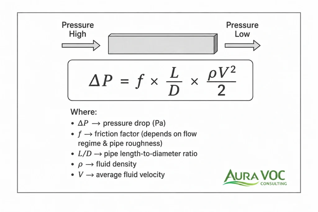
This is why pressure drop troubleshooting should include airflow verification at relevant process points. A total system differential pressure reading can confirm that resistance has changed, but it does not show whether each source is still receiving the required exhaust flow. Branch balancing, damper positions, hood conditions, and process-side measurements often need to be reviewed together.
Fan Speed, Motor Current, and Available Static Pressure Margin
A pressure drop increase becomes more serious when the fan is already operating near its practical limit. In systems equipped with a variable frequency drive, the fan may maintain airflow for some time by increasing speed. This can mask a developing restriction until the fan reaches a speed limit, motor current limit, or noise and vibration constraint.
For fixed-speed fans, the response is different. As system resistance increases, the operating point shifts along the fan curve and airflow may decrease. The plant may not see a dramatic alarm immediately, but the exhaust system can gradually move away from its design airflow. In this condition, pressure drop readings, motor current, and airflow measurements must be interpreted together.
Motor amperage alone can also be misleading. Depending on fan type and operating point, a fouled system may show increased motor load, reduced flow, or a combination of both. Troubleshooting should include fan speed, fan curve data, damper position, belt condition where applicable, impeller condition, and actual airflow readings. Without this context, it is easy to treat a fan limitation as an oxidizer fouling problem, or to overlook a restriction because the VFD is still compensating.
Production Limits Caused by Rising System Resistance
Pressure drop problems often become visible when production increases. A system that appears acceptable at partial load may not have enough margin at full exhaust volume. This is common after production expansion, added process vents, recipe changes, or increased oven and dryer throughput.
When the fan cannot maintain required flow at peak production, the plant may need to reduce line speed, limit simultaneous operation of multiple sources, or delay connecting additional equipment. In this situation, pressure drop is no longer only a maintenance concern. It becomes a production constraint and a capacity issue.
Before adding new exhaust connections to an existing oxidizer system, the plant should review the fan curve, duct losses, oxidizer pressure drop, stack backpressure, and any pre-treatment equipment. Even if the oxidizer has sufficient thermal capacity for the added VOC load, the exhaust system may not have enough static pressure margin to move the additional air volume.
Combustion Stability and Residence Time Considerations
Abnormal airflow can also affect oxidizer operation. Thermal oxidizers are designed around specified flow, temperature, residence time, turbulence, and destruction conditions. For technical background, the U.S. EPA describes thermal oxidizers as combustion devices used to control VOC, CO, and volatile HAP emissions. If airflow drops below expected levels, or if false air enters the system through leaks, the control system may respond in ways that affect burner firing rate, chamber temperature, dilution air, or heat recovery balance.
For recuperative systems, fouling across the heat exchanger can change both pressure drop and thermal performance. For RTOs, media bed plugging or valve leakage can affect flow distribution between chambers. For catalytic oxidizers, catalyst bed fouling can create uneven flow paths and localized performance issues.
Pressure drop should therefore be considered alongside temperature trends, burner behavior, valve position, oxygen readings where available, and process exhaust composition. A pressure drop deviation that seems minor on a gauge may be significant if it coincides with airflow instability, fan limits, poor capture, or repeated maintenance interventions.
Establishing a Pressure Drop Baseline Before Troubleshooting
Effective troubleshooting requires a reliable reference point. Without a baseline, the plant may know that pressure drop is “high,” but not where it has changed, how fast it has changed, or whether the change is related to production conditions.
A useful baseline is not a single total pressure drop value. It is a set of operating data recorded when the system is known to be clean, stable, and operating at a defined production condition. For many plants, the best opportunity to establish this reference is after commissioning, after a planned shutdown cleaning, or after major maintenance on the fan, ductwork, oxidizer internals, or pre-treatment equipment.
Clean-System Baseline After Commissioning or Shutdown Cleaning
A clean-system baseline should be recorded when the system has been inspected, cleaned, and returned to normal operation. This provides the reference point for future pressure drop trends. If pressure drop begins increasing from that baseline, the plant can evaluate whether the rise is gradual and expected, or rapid enough to indicate abnormal fouling or process carryover.
For industrial systems handling solvent-laden exhaust, the clean baseline should also document the process condition at the time of measurement. A baseline taken during low production may not be useful for evaluating a future pressure drop problem at maximum line speed. The most useful records identify the operating mode, production rate, airflow, fan speed, oxidizer temperature, and connected exhaust sources.
Sectional Pressure Drop Measurement Points
Total system pressure drop can confirm that resistance has changed, but sectional measurements are needed to locate the problem. Important measurement points may include filters, demisters, knock-out pots, duct sections, heat exchangers, RTO media beds, catalyst beds, fan inlet and outlet, dampers, silencers, stacks, scrubbers, and other downstream equipment.
In practice, the most valuable measurements are those that separate likely restriction points. For a recuperative oxidizer, pressure drop across the heat exchanger is often critical. For an RTO, pressure drop across each media bed can help identify plugging or uneven flow distribution. For catalytic systems, catalyst bed differential pressure should be trended because particulate or condensed material can affect both flow and catalyst exposure.
Measurement reliability matters. Pressure taps should be located away from elbows, transitions, dampers, or highly turbulent duct sections where possible. In wet or sticky exhaust service, taps may require cleaning, purging, heat tracing, or routine inspection to remain reliable.
Comparing Pressure Drop at Similar Airflow and Fan Speed
Pressure drop varies with flow. Comparing readings taken at different airflow rates, fan speeds, damper positions, or production loads can lead to incorrect conclusions. A higher pressure drop during peak production may be normal if airflow is also higher. A similar pressure drop at reduced airflow may indicate a developing restriction.
For this reason, pressure drop trends should be reviewed together with airflow, fan speed, motor current, damper position, and production status. On VFD-controlled systems, a stable pressure drop reading may not mean the system is stable if fan speed has increased to maintain flow. The VFD may be absorbing the effect of fouling until available speed or motor capacity is exhausted.
Baseline Data to Keep in the Maintenance File
A practical maintenance file should include total and sectional pressure drop readings, measured airflow, fan speed, motor current, oxidizer operating temperature, inlet temperature, process exhaust temperature, VOC load where available, moisture conditions, damper positions, production mode, and recent maintenance actions.
The record should also include unusual process conditions, such as new solvent blends, resinous materials, high-moisture campaigns, particulate-generating products, or temporary bypass arrangements. These details help distinguish equipment deterioration from process-driven changes.
A well-documented baseline allows the plant to move from general troubleshooting to targeted investigation. It supports shutdown planning, alarm interpretation, and decisions about cleaning, fan review, duct modifications, upstream filtration, or technology changes.
High Thermal Oxidizer Pressure Drop: Common Causes and Verification Checks
High pressure drop usually indicates that the exhaust system has developed additional resistance beyond the clean operating condition. The restriction may be inside the oxidizer, upstream in the process ductwork, across pre-treatment equipment, or downstream at the stack or silencer. Troubleshooting should avoid assuming that the oxidizer vessel itself is the source.
A high pressure drop condition should also be reviewed with fan data. If the fan is running faster than normal, drawing higher current, or operating near the upper end of the VFD range, the system may already be compensating for a developing restriction. If the fan is fixed-speed, reduced airflow may be the first operational consequence.
Heat Exchanger Fouling in Recuperative Thermal Oxidizers
In recuperative thermal oxidizers, the heat exchanger is often one of the most pressure-drop-sensitive components. Fouling can occur when particulate, condensable organics, resinous materials, plasticizers, oils, or corrosion products accumulate on heat transfer surfaces. Coating ovens, resin processing, pharmaceutical dryers, and chemical exhaust streams can all generate deposits that are not fully visible from external operating data.
A rise in pressure drop across the heat exchanger should be compared with changes in thermal performance. If pressure drop increases while heat recovery decreases, fouling is likely affecting both flow and heat transfer. If the pressure drop increases shortly after a process change, the plant should review solvent composition, exhaust temperature, moisture content, and particulate carryover. Cleaning may restore capacity, but repeated fouling usually indicates an upstream process or pre-treatment issue.
Ceramic Media Plugging in Regenerative Thermal Oxidizers
In regenerative thermal oxidizers, pressure drop across the ceramic media beds is a key diagnostic point. Plugging can result from particulate carryover, condensed organics, salts, catalyst fines from upstream equipment, or corrosion-related solids. In some cases, deposits concentrate in the lower portion of the bed where gas temperature, flow direction changes, or condensation conditions are most unfavorable.
Uneven media bed pressure drop can also indicate flow imbalance between chambers. If one bed shows a different trend from the others, the issue may involve media condition, valve leakage, flow distribution, or localized accumulation. RTO troubleshooting should review chamber temperature patterns, valve operation, purge performance, and pressure drop across each bed rather than relying only on total system differential pressure.
Catalyst Bed Pressure Drop in Catalytic Oxidizers
Catalytic oxidizers are sensitive to particulate and aerosol loading because the catalyst surface must remain exposed to the gas stream. A rising pressure drop across the catalyst bed may indicate particulate fouling, condensed material, masking of catalyst channels, or mechanical degradation of catalyst modules. The operational risk is not only higher resistance; blocked or masked channels can also create uneven flow distribution through the catalyst bed.
When catalyst bed pressure drop increases, the plant should review upstream filtration, mist elimination, process aerosol content, and any recent changes in solvent or additive chemistry. A catalyst bed that is repeatedly fouled may need better upstream separation or a review of whether the process exhaust is suitable for catalytic oxidation without additional conditioning.
Filter, Demister, or Pre-Separator Loading
Upstream protection equipment is installed to reduce fouling risk in the oxidizer, but it also becomes part of the pressure drop profile. Filters, demisters, cyclones, knock-out pots, and pre-separators should be trended separately. A loaded pre-filter may protect the oxidizer but reduce exhaust airflow if it is not replaced or cleaned within the operating window.
This is a common tradeoff in industrial systems. Adding filtration can reduce heat exchanger, catalyst, or media fouling, but it introduces another maintenance-dependent pressure drop component. The filter specification should consider particle size, loading rate, moisture, solvent compatibility, temperature, and allowable differential pressure. A filter that performs well on clean dry air may not be suitable for warm solvent-laden exhaust with sticky aerosol.
Condensation, Aerosols, and Sticky Deposits in VOC Exhaust
Condensation is a frequent cause of pressure drop problems because it can convert a vapor-phase exhaust issue into a deposit formation issue. If duct temperature drops below the dew point of water, solvent, oil mist, or other condensable components, liquid films can collect particulate and form sticky deposits. The resulting buildup may occur in horizontal duct runs, elbows, low points, heat recovery sections, dampers, or stack components.
Troubleshooting should review exhaust temperature profiles, duct insulation, outdoor duct sections, startup and shutdown conditions, and batch process phases with high moisture or solvent loading. A system may operate without issues during steady production but develop deposits during cold starts, low-flow periods, product changeovers, or washdown-related moisture events.
Sector-specific patterns are common. Coating lines may carry overspray, resin aerosols, plasticizers, and oven condensables. Pharmaceutical dryers may produce solvent-rich phases followed by powder carryover. Food processing can add moisture, oils, and particulate. Chemical reactor vents may introduce salts, corrosive compounds, or polymerizing vapors.
Damper Position Errors and Actuator Failures
A partially closed damper can create a high pressure drop condition that resembles fouling. This may result from actuator failure, incorrect position feedback, mechanical binding, damaged linkage, control logic errors, or a manual damper left in the wrong position after maintenance. In multi-branch exhaust systems, one damper issue can also shift flow away from one source and toward another.
Damper verification should include physical inspection where safe and practical, not only control screen feedback. Position indicators can be miscalibrated, linkages can slip, and blades can deform or foul. Damper issues are especially important in systems with bypasses, heat exchanger isolation dampers, RTO valves, purge dampers, and production-line balancing dampers.
Fan Impeller Fouling, Belt Slip, and VFD Limitations
Fan underperformance can be mistaken for a pressure drop problem because the system may show reduced airflow and abnormal static pressure. Common causes include impeller fouling, worn or slipping belts, incorrect rotation after maintenance, bearing problems, blade wear, inlet restrictions, or VFD speed limits. A dirty impeller can reduce fan efficiency and change the fan’s actual performance relative to the curve.
Fan troubleshooting should include motor current, fan speed, vibration, inlet and outlet pressure, belt condition, impeller inspection, and comparison with the fan curve. If the fan is already near its speed or current limit, further pressure drop increases may immediately reduce airflow. This is particularly important before adding new exhaust points to an existing VOC abatement system.
Stack, Silencer, or Downstream Restriction
Downstream components can also contribute to high pressure drop. Silencers, stacks, rain caps, bird screens, outlet dampers, scrubbers, and discharge ductwork may accumulate corrosion products, solids, or debris. Rain ingress and poor drainage can create liquid accumulation, while corrosion can reduce open area or create internal roughness.
Stack and silencer restrictions are sometimes overlooked because they are outside the oxidizer package. If pressure drop remains high after cleaning upstream components, the downstream path should be inspected. This is especially relevant where acidic compounds, halogenated VOCs, high moisture, or outdoor discharge sections are present.
Low or Unexpectedly Reduced Pressure Drop: Leakage, Bypass, and Measurement Errors
A low pressure drop reading should not automatically be treated as a positive result. If pressure drop falls without a known reduction in airflow or after no maintenance action, the system may have developed a leakage path, bypass condition, missing internal resistance, or instrumentation fault. Low pressure drop can be just as important as high pressure drop because it may indicate that part of the exhaust stream is no longer following the intended flow path.
Bypass Damper Leakage or Incorrect Bypass Position
Bypass dampers are useful for maintenance, startup, emergency protection, or process isolation, but they require reliable sealing and control. If a bypass damper leaks or remains partially open, measured pressure drop across the oxidizer may decrease while untreated or partially treated exhaust avoids the intended path. This can also dilute temperature signals or create misleading airflow assumptions.
Verification should include damper position, actuator response, seal condition, interlocks, and temperature changes around the bypass path. In systems with automatic bypass logic, alarm history and control sequences should be reviewed to confirm that bypass operation has not occurred during normal production.
Access Door, Expansion Joint, or Seal Leakage
Air leakage through access doors, expansion joints, flange gaskets, fan inlet connections, or inspection ports can reduce measured pressure drop or change the apparent process airflow. False air ingress can dilute the VOC stream, affect temperature control, and change fan loading. In negative-pressure sections, leaks may not release exhaust outward but can still distort system operation by drawing in ambient air.
Seal leakage is often identified through inspection, smoke testing where appropriate, temperature deviations, oxygen readings, or unexplained airflow imbalance. After maintenance, access doors and gaskets should be checked carefully, especially on units that operate through frequent thermal cycling.
Missing, Damaged, or Shifted Internal Components
If internal components are missing, damaged, or displaced, pressure drop may decrease because the gas is no longer flowing through the intended restriction. This can occur with shifted baffles, damaged heat exchanger internals, displaced ceramic media, collapsed catalyst modules, failed retaining screens, or removed packing in ancillary equipment.
A low pressure drop condition of this type may coincide with poor temperature distribution, unusual noise, vibration, or reduced treatment performance. Internal inspection may be required during shutdown if operating data suggests a sudden reduction in resistance without a corresponding process explanation.
Differential Pressure Instrumentation Errors
Instrumentation faults are a common source of misleading pressure drop readings. Pressure taps may plug with condensate or solids, impulse lines may leak, transmitters may drift, or local gauges may be installed at unsuitable locations. A pressure tap in a turbulent duct section or near an elbow may not provide a stable representative reading.
Before mechanical work is planned, the pressure drop measurement should be verified. This includes checking zero calibration, tubing condition, tap cleanliness, transmitter range, and comparison against a temporary local gauge. In wet or sticky exhaust service, pressure taps may require regular cleaning or purging to remain reliable.
Variable or Unstable Pressure Drop During Operation
Variable pressure drop can be more difficult to diagnose than a steady increase because it may depend on production phase, damper movement, fan control response, or process chemistry. The key is to correlate pressure drop changes with operating events rather than averaging the trend over a shift or production campaign.
Batch Exhaust Flow Variation from Dryers, Reactors, or Coating Lines
Batch processes often create changing exhaust conditions. Pharmaceutical dryers, chemical reactors, coating lines, and food dryers may have different airflow, moisture, temperature, and vapor loading during charging, heating, drying, solvent removal, cooling, or cleaning phases. Pressure drop may rise only during one part of the batch cycle.
Troubleshooting should compare pressure drop trends with batch step timing. If the pressure drop spike corresponds to high moisture release, solvent boil-off, or particulate entrainment, the issue may be process-driven rather than equipment-driven. This can affect decisions about duct temperature control, filtration, demisting, or operating sequence changes.
Damper Hunting and Control Loop Instability
Unstable pressure drop may be caused by damper hunting or poor control loop tuning. If dampers continuously adjust to maintain duct pressure, oven balance, or oxidizer flow, the measured pressure drop may fluctuate even when the physical condition of the system has not changed. This can be made worse by oversized dampers, slow actuators, poor feedback signals, or interacting control loops.
Reviewing trend data for damper position, fan speed, duct pressure, and airflow can help distinguish control instability from fouling. If pressure drop fluctuations follow damper movement rather than production load, the corrective action may involve control tuning, actuator maintenance, or revised balancing procedures.
VFD Response Masking a Developing Restriction
A VFD-controlled fan can maintain exhaust flow while pressure drop increases, provided speed and motor capacity are available. This can make the system appear stable until the fan reaches its operating limit. By the time airflow starts to fall, the underlying restriction may already be significant.
For this reason, fan speed trend is often as important as pressure drop trend. A gradual rise in fan speed at constant production rate can indicate increasing resistance even if airflow remains unchanged. Maintenance teams should treat rising VFD speed or motor current as early indicators of fouling or loading.
Process Recipe Changes Affecting Deposits or Condensation
A change in solvent blend, solids content, resin formulation, drying temperature, or moisture release can alter the way deposits form in the exhaust system. The pressure drop problem may appear after a new product campaign even if the oxidizer hardware has not changed.
Process engineers should review whether new materials have different condensation behavior, higher boiling components, sticky aerosols, or increased particulate carryover. Where recipe changes are frequent, pressure drop trends should be reviewed by product or campaign, not only by calendar date.
Pressure Drop Changes During Peak Production
Some restrictions only become operationally significant at maximum flow. A duct section, media bed, filter, or silencer may appear acceptable at partial load but create excessive resistance during peak production. This can lead to intermittent airflow loss, fan speed alarms, or process ventilation complaints during high-throughput periods.
Testing at normal maximum operating conditions is often necessary to confirm whether the system has enough pressure drop margin. A troubleshooting review based only on low-load readings may miss the condition that is limiting production.
Step-by-Step Troubleshooting Method for Thermal Oxidizer Pressure Drop
A pressure drop problem should not automatically lead to oxidizer cleaning or fan adjustment. Before opening the unit or scheduling downtime, the plant should confirm whether the pressure change is real, where it occurs, and whether it appears only under specific operating conditions such as peak production, cold startup, solvent boil-off, or batch drying.
Step 1 — Confirm the Pressure Drop Reading
Start with the measurement. Differential pressure transmitters, local gauges, pressure taps, tubing, and impulse lines should be checked before assuming a mechanical restriction. In solvent-laden, wet, or particulate service, pressure taps can plug, impulse lines can collect liquid, and transmitter zero can drift.
A local temporary gauge can be useful for confirming the installed transmitter before maintenance work begins. A plugged high-pressure tap can produce a falsely low reading. A partially blocked low-pressure tap can produce a falsely high reading. Taps located close to elbows, dampers, transitions, or turbulent duct sections may also give unstable readings that are not representative of the actual system condition.
Step 2 — Compare Against Historical Trend Data
Pressure drop should be reviewed together with airflow, fan speed, motor current, oxidizer temperature, inlet temperature, process exhaust temperature, damper position, and production rate. These variables show whether the system is becoming more restrictive, whether the fan is compensating, or whether the operating condition has simply changed.
For example, a higher pressure drop at higher airflow may be normal. A similar pressure drop at reduced airflow may indicate a restriction. On a VFD-controlled fan, rising fan speed at the same production rate can be an early sign of fouling even if airflow has not yet decreased.
The pattern of the change matters. Pressure drop that increases only at full production suggests limited fan margin or a restriction that becomes significant at peak flow. Pressure drop that returns quickly after cleaning suggests upstream carryover, condensation, sticky aerosol, or process chemistry rather than cleaning interval alone. Pressure drop that falls suddenly after maintenance should trigger checks for bypass position, access door seals, missing internals, or instrument error before assuming improvement.
Step 3 — Separate Fan Problems from System Restrictions
Reduced airflow does not always mean the system is plugged. The fan may be underperforming because of impeller fouling, belt slip, worn sheaves, incorrect rotation, inlet restriction, bearing issues, VFD limits, or operation away from the expected fan curve.
A useful review compares actual fan speed, static pressure, airflow, and motor current against the fan curve. For fixed-speed fans, increased system resistance generally shifts the operating point toward lower airflow. For VFD fans, speed may increase to hold airflow until the drive, motor current, vibration, noise, or fan curve limit is reached. For damper-controlled systems, dampers may open further and hide the problem until no control authority remains.
Step 4 — Isolate the Restriction by Section
Total system pressure drop confirms that resistance has changed; sectional pressure drop identifies where the change has occurred. Measurements should be taken across filters, demisters, duct sections, heat exchangers, RTO media beds, catalyst beds, silencers, stacks, scrubbers, and major dampers where access points are available.
For example, if total system pressure drop has increased by 800 Pa and 650 Pa of that increase is across the recuperative heat exchanger, inspection should focus on heat exchanger fouling. If the increase is distributed across long duct runs, elbows, and downstream stack components, condensation, corrosion, or deposit formation outside the oxidizer package may be more likely.
Step 5 — Review Recent Process and Production Changes
Pressure drop problems often follow a process change. Relevant changes include new solvent blends, higher solids content, increased line speed, added exhaust branches, higher moisture release, changed dryer temperature, different resin or coating formulation, powder carryover, or cleaning cycles that introduce humidity.
A system that was stable on one product campaign may foul quickly on another. The maintenance team may see this as an oxidizer issue, while the underlying cause is a change in exhaust chemistry or physical loading.
Step 6 — Inspect Mechanical Components During Shutdown
Shutdown inspection should be planned around the suspected restriction. If trend data points to the fan, inspect impeller condition, belts, bearings, rotation, inlet conditions, and vibration. If the restriction is across the heat exchanger, inspect for deposits, corrosion, blocked passages, and access limitations. If pressure drop is high across an RTO bed, inspect media condition, bed support, valve leakage paths, and signs of uneven flow.
Inspection planning should also account for cooling time, lockout/tagout, bypass isolation, confined-space requirements where applicable, and safe handling of deposits that may contain solvent residue, corrosive material, combustible solids, or cleaning chemicals.
Step 7 — Select Corrective Actions Based on Root Cause
Corrective action should match the verified cause. Cleaning is appropriate when sectional pressure drop confirms fouling. Fan repair is appropriate when airflow is low without a corresponding increase in resistance. Damper repair is appropriate when position feedback does not match physical blade position. Insulation, heat tracing, drainage, or operating sequence changes become relevant when deposits correlate with cold duct sections or startup condensation.
Repeated cleaning without source control should be treated as a warning. It may indicate the need for upstream filtration, demisting, temperature control, duct modification, process-side changes, or a review of whether the installed oxidizer configuration is suitable for the current exhaust stream.
Maintenance Actions That Reduce Pressure Drop Recurrence
Maintenance should be based on operating evidence, not only fixed calendar intervals. OSHA ventilation requirements also recognize that pressure drop changes can indicate partial blockage requiring cleaning and return to normal operating condition. Pressure drop trends are useful because they show how quickly resistance returns after cleaning and whether the loading rate changes with product campaign, season, production rate, or process modification.
Cleaning Triggers Based on Pressure Drop Trend
Cleaning should be triggered by differential pressure increase, airflow loss, fan speed increase, motor current trend, or production impact. A fixed interval may be too long during high-loading campaigns and unnecessarily short during cleaner operating periods.
The trigger should also consider operating mode. A pressure drop value that is acceptable at partial production may be limiting at full production. For variable-flow systems, alarms and cleaning thresholds should be reviewed against airflow, fan speed, and production status rather than treated as fixed values independent of operating condition.
Heat Exchanger, Media Bed, Catalyst Bed, and Duct Cleaning Access
Poor access increases downtime and often limits cleaning effectiveness. Access doors, removable duct sections, drains, isolation dampers, and safe entry provisions should be reviewed when recurring pressure drop problems are present.
Cleaning access should match the components that are likely to foul. Recuperative heat exchangers need access to affected passages. RTO media beds may require access for inspection, removal, or controlled cleaning. Catalyst modules need inspection access without damaging the catalyst face. Duct sections with known low points or condensation risk should have cleanouts and drains.
Pressure Tap and Instrument Line Maintenance
Pressure taps should be included in routine maintenance. Plugged taps can cause false stability or false alarms. In wet or sticky service, purge arrangements or more accessible tapping points may be required.
Instrument maintenance should include zero checks, transmitter range verification, impulse line inspection, condensate removal, and comparison with local gauges where practical. A pressure drop trend is only useful if the measurement remains reliable over time.
Fan and Damper Inspection During Planned Shutdowns
Fan and damper checks should include impeller fouling, belt tension, sheave wear, bearings, actuator travel, damper blade alignment, linkage wear, and position feedback. These components directly affect the ability to maintain exhaust flow.
Damper inspections should not rely only on control system position feedback. Physical blade position, binding, corrosion, gasket condition, and linkage integrity should be checked where safe access is available. In RTOs and systems with bypass dampers, leakage and incomplete closure can affect both pressure drop and flow path integrity.
Post-Cleaning Baseline Reset
After cleaning or major maintenance, record the new baseline: total and sectional pressure drop, airflow, fan speed, motor current, damper positions, oxidizer temperature, inlet temperature, and production condition. This becomes the reference for future diagnosis.
A useful post-cleaning record also documents what was found, where deposits were heaviest, how cleaning was performed, whether drains or taps were plugged, and whether fan or damper components were adjusted. This helps distinguish a normal loading cycle from a recurring root-cause problem.
Pressure Drop, Fan Energy, and Airflow Capacity
Pressure drop becomes an operating constraint when the fan can no longer maintain the required exhaust flow at acceptable speed, current, noise, vibration, or control stability. In many plants, the first consequence of increasing pressure drop is not a direct failure of the oxidizer. It is the gradual loss of airflow margin.
How Rising System Resistance Changes the Fan Operating Point
As duct deposits, filter loading, media plugging, or heat exchanger fouling increase system resistance, the fan operating point changes. With a fixed-speed fan, the result is typically lower airflow. The oxidizer may remain at temperature, but the process hoods, enclosures, ovens, or vents may no longer receive the same exhaust volume.
With a VFD-controlled fan, the control system may increase fan speed to maintain the airflow or duct pressure setpoint. This can keep production running, but it also hides the developing restriction until speed, motor current, or mechanical limits are reached.
VFD Compensation and Motor Current Limits
VFD trend data is useful for early diagnosis. A fan that required 42 Hz after the last shutdown but now requires 50 Hz for the same production condition is showing a loss of system margin. If motor current is also increasing, the plant should not wait for a high-pressure-drop alarm before investigating.
VFD compensation has limits. Higher speed may increase electrical load, vibration, bearing stress, noise, and sensitivity to duct imbalance. The plant should also confirm that the fan is still operating in a stable region of the fan curve.
When Pressure Drop Reduces Flow Instead of Increasing Power
Not every system shows higher motor current when resistance increases. Depending on fan type and operating point, airflow may fall while motor load remains steady or even decreases. This is why pressure drop troubleshooting should not rely on amperage alone.
A process area complaint, loss of hood capture, unstable oven balance, or reduced enclosure negative pressure may be the first indication that airflow has fallen. Field airflow measurements are often needed to confirm whether design exhaust rates are still being achieved.
Cleaning as an Airflow and Energy Recovery Measure
Cleaning should be evaluated in terms of recovered airflow, recovered fan margin, and reduced system resistance. In a VFD system, cleaning may allow the same exhaust flow at lower speed and lower electrical demand. In a fixed-speed system, cleaning may restore airflow that had been lost gradually.
The post-cleaning baseline should include differential pressure, airflow, fan speed, motor current, damper position, and production condition. Without this record, it is difficult to quantify how much capacity was recovered.
Fan Margin Review Before Adding New Process Vents
Before connecting new process vents to an existing thermal oxidizer system, the review should include more than oxidizer thermal capacity. The fan curve, duct losses, heat exchanger or media pressure drop, stack backpressure, damper positions, and available VFD range should all be checked.
A plant may have enough combustion chamber capacity for additional VOC load but insufficient static pressure margin to move the added air. In that case, production expansion can create a pressure drop and airflow problem even if the oxidizer itself appears correctly sized from a temperature or residence-time perspective.
Engineering Tradeoffs When Correcting Pressure Drop Problems
Pressure drop corrections often involve tradeoffs. Reducing resistance in one part of the system may create a maintenance, energy, wastewater, or process-control consequence elsewhere.
Larger Ductwork vs Transport Velocity for Particulate-Laden Exhaust
Larger ductwork can reduce static pressure loss, but lower velocity may allow particulate, resin mist, powder, overspray, oil droplets, or condensed solids to settle in horizontal runs and elbows. Higher velocity can improve transport but increases fan energy, noise, erosion risk, and balancing sensitivity.
A practical review should consider actual operating flow, minimum transport velocity, duct slope, cleanout access, elbow geometry, and whether deposits are forming in specific low-velocity areas. In some systems, the best answer is not simply a larger duct but a combination of velocity control, better drainage, improved access, and upstream reduction of solids or aerosols.
Added Filtration vs Added Static Pressure
Upstream filtration, demisting, or knock-out equipment can protect heat exchangers, RTO media, and catalyst beds. The tradeoff is that the protection device becomes another pressure drop component requiring inspection, cleaning, replacement, and spare parts.
Filter selection should be based on real exhaust conditions: particle size, sticky aerosol content, moisture, solvent compatibility, temperature, loading rate, and allowable terminal pressure drop. A filter that performs well in dry service may plug quickly in warm exhaust containing resinous mist or condensable organics.
Heat Recovery Efficiency vs Fouling Sensitivity
Higher heat recovery can reduce fuel demand, but the selected heat recovery design must be compatible with the exhaust stream. Compact recuperative heat exchangers may have tighter passages that are more sensitive to sticky deposits. RTO media with high heat transfer surface may also create higher baseline pressure drop or greater plugging risk if particulate loading is not controlled.
The practical question is not only “What is the thermal efficiency?” but also “How will this equipment behave after several months of real process operation, and how will it be cleaned?” A design with slightly lower heat recovery but better fouling tolerance and access may be more appropriate for some exhaust streams.
Wet Pre-Treatment vs Wastewater and Sludge Handling
Wet pre-treatment can reduce particulate, acid gas, soluble compounds, or condensable material before the oxidizer, but it introduces liquid handling. Scrubbers, quench systems, and wet collectors require blowdown control, pH management, mist elimination, solids removal, and sludge or wastewater routing.
This tradeoff is important when the plant is trying to solve fouling by adding a wet step. The air-side pressure drop problem may improve, but the plant may create a wastewater or maintenance bottleneck if liquid handling is underestimated.
Redundancy and Access Design vs Installed Cost and Footprint
Parallel filters, isolation dampers, larger access doors, removable duct sections, and bypass arrangements can reduce downtime during cleaning and inspection. They also increase installed cost, footprint, control complexity, and maintenance requirements.
For plants with short shutdown windows or continuous production, access and isolation may be more valuable than a lower initial installation cost. Poor access often turns a manageable pressure drop issue into a repeated outage problem.
Temporary Cleaning vs Process-Side Modification
If pressure drop returns quickly after cleaning, repeated cleaning may only be treating the symptom. Process-side changes may be needed when fouling is linked to product formulation, atomization, drying profile, cleaning cycles, moisture release, or exhaust temperature.
Examples include reducing aerosol carryover from coating lines, preventing powder entrainment from dryers, controlling cold duct condensation, or adding pre-separation before the oxidizer. The maintenance strategy should be adjusted only after the plant understands whether the loading is normal, abnormal, or driven by a process change.
Wastewater and Liquid Handling Implications During Pressure Drop Correction
Pressure drop correction can create secondary liquid waste streams. This is often overlooked when the immediate objective is to remove deposits from ductwork, heat exchangers, RTO media, or upstream equipment.
Washdown Water from Duct, Heat Exchanger, or Media Cleaning
Wet cleaning can produce water containing VOC residues, particulate, resin, oils, corrosion products, cleaning chemicals, acidic compounds, or alkaline detergents. Before cleaning begins, the plant should define where the liquid will drain, how it will be contained, whether solids removal is needed, and whether the wastewater can enter the existing treatment system.
In some cases, the cleaning waste may need separate collection and off-site disposal. This should be planned before opening drains or washing internals. If the cleaning contractor, maintenance team, and wastewater team are not aligned before the work starts, the cleaning activity can create delays after the oxidizer is already opened.
Condensate Collection from Low-Temperature Duct Sections
Condensate from ductwork or heat recovery sections can contain dissolved organics, suspended solids, corrosion products, and low-pH or high-pH components depending on the exhaust stream. Drains, traps, containment, and inspection points should be considered where low-temperature duct sections are unavoidable.
Uncontrolled condensate can also create new pressure drop problems by binding particulate into sticky deposits or corroding internal surfaces. In outdoor ductwork or long horizontal runs, condensate control may be as important as oxidizer cleaning in preventing recurrence.
Scrubber or Quench Blowdown Added to Control Fouling
A scrubber or quench may protect downstream equipment, but it adds blowdown and sludge management. Blowdown rate, pH control, dissolved organics, solids loading, mist eliminator pressure drop, and maintenance access all affect long-term reliability.
Mist carryover from a wet system can also create downstream deposits if separation is poor. For this reason, wet pre-treatment should be evaluated as part of the full VOC abatement system, not as a separate add-on.
Avoiding Secondary Maintenance Problems
Wet systems introduce their own failure modes: plugged spray nozzles, scaled internals, blocked drains, mist eliminator fouling, corrosion, biological growth in stagnant sections, and sludge buildup. These risks may be acceptable, but they should be understood before using wet treatment to solve a pressure drop issue.
A pressure drop problem should not simply be moved from the oxidizer to the wastewater system or scrubber. The full operating burden needs to be considered, including maintenance staffing, wastewater capacity, chemical consumption, solids handling, and inspection access.
Technology-Specific Pressure Drop Considerations
Each oxidizer configuration has different pressure-drop-sensitive components. Troubleshooting is more effective when measurements focus on the components that are most likely to restrict flow in that technology. The European Commission WGC BREF provides technical context for waste gas management and treatment systems in the chemical sector.
Direct-Fired Thermal Oxidizers
Direct-fired thermal oxidizers usually have fewer internal heat recovery restrictions than recuperative or regenerative systems. Pressure drop problems are more likely to involve ductwork, dampers, fan performance, burner section internals, stack backpressure, or downstream equipment.
Key checks include total system static pressure, fan operating point, damper position, stack condition, and any upstream filters or demisters. Because direct-fired systems may handle higher fuel input without heat recovery, airflow capacity and fan margin often become the main operating constraints.
Recuperative Thermal Oxidizers
For recuperative systems, the heat exchanger is a primary diagnostic point. Rising pressure drop across the heat exchanger should be reviewed with heat recovery performance, outlet temperature, burner firing trend, and process exhaust composition.
A heat exchanger that fouls repeatedly may require improved upstream filtration, demisting, duct temperature control, or changes to cleaning access. If fouling reduces both heat transfer and open flow area, the plant may see higher fan demand and higher fuel use at the same production rate.
Regenerative Thermal Oxidizers
RTO pressure drop troubleshooting should separate the media beds, switching valves, purge system, and common ductwork. A total pressure drop reading alone may not identify whether one bed is plugging, a valve is leaking, or flow distribution is uneven.
Useful checks include pressure drop across each bed, chamber temperature trends, valve position and seal condition, purge timing, bake-out history, and signs of particulate or condensable carryover. A bed with abnormal pressure drop compared with the others should be inspected for localized plugging or media damage.
Catalytic Oxidizers
Catalytic oxidizers require attention to catalyst bed differential pressure and upstream exhaust cleanliness. Particulate, mist, condensed material, or process additives can mask catalyst channels and increase pressure drop while also reducing effective catalyst exposure.
Useful checks include catalyst bed differential pressure, pre-filter condition, catalyst face inspection, inlet temperature, process aerosol content, and recent recipe or solvent changes. If catalyst fouling is recurring, the plant should review upstream filtration, mist elimination, and whether catalytic oxidation is compatible with the exhaust stream without additional conditioning.
When Pressure Drop Indicates Poor Technology Fit
Recurring pressure drop problems may indicate that the current abatement configuration is not well matched to the process exhaust. This is more likely when the system handles sticky aerosols, high particulate loading, condensable VOCs, corrosive compounds, high moisture, salts, or polymerizing vapors.
In these cases, the review should look beyond cleaning frequency. The plant may need pre-treatment, duct temperature control, different heat recovery design, revised operating sequence, or a broader technology selection review.
Troubleshooting Checklist Before Engineering Review
Before an engineering review, the plant should assemble enough operating information to avoid repeating basic checks. The goal is to separate measurement error, fan limitation, mechanical restriction, and process-driven loading.
Operating Data to Collect
Collect total and sectional pressure drop, measured airflow, fan speed, motor current, VFD frequency, oxidizer temperature, inlet temperature, process exhaust temperature, production rate, VOC load where available, moisture conditions, and damper positions.
The data should be tied to operating mode. A trend screenshot should identify whether the system was at low load, normal production, peak production, startup, shutdown, cleaning cycle, or a specific batch step.
Mechanical Items to Inspect
Inspect filters, demisters, ductwork, dampers, actuators, expansion joints, fan impeller, belts, bearings, heat exchanger passages, RTO media, catalyst bed face, stack, silencer, drains, access doors, gaskets, and pressure taps.
Inspection should focus first on the section where the pressure drop has changed. Opening the oxidizer without confirming the affected section can waste shutdown time and miss restrictions in ductwork, stack components, or pre-treatment equipment.
Process Questions to Answer
Identify whether there have been recipe changes, solvent substitutions, increased production rates, new exhaust connections, higher moisture release, increased solids or aerosol loading, different dryer temperatures, new cleaning practices, or changes in operating sequence.
The timing of the pressure drop change should be compared with these process changes. If pressure drop increased after a product campaign began, after a new vent was connected, or after a solvent blend changed, the root cause may not be mechanical wear.
Documentation to Prepare
Prepare the P&ID, fan curve, layout drawings, oxidizer data sheet, maintenance logs, alarm history, trend screenshots, airflow test reports, damper position records, filter replacement history, and recent inspection notes.
For recurring issues, include before-and-after-cleaning data. The difference between pre-cleaning and post-cleaning conditions is often the most useful evidence for identifying whether fouling is localized, distributed, or process-driven.
When to Escalate Pressure Drop Issues to Engineering Review
Not every pressure drop change requires a detailed engineering study. Some issues are routine filter loading or scheduled cleaning. Escalation is appropriate when the trend affects airflow, production, fan margin, maintenance frequency, or the ability to operate the VOC abatement system within its intended limits.
Pressure Drop Returns Quickly After Cleaning
If pressure drop returns quickly after cleaning, the source of fouling has not been corrected. Possible causes include upstream aerosol carryover, particulate loading, condensation, corrosion, solvent chemistry, product formulation, or poor duct temperature control.
Repeating the same cleaning cycle may keep the system running temporarily, but it does not address why the deposits are forming. An engineering review should evaluate process conditions, duct layout, pre-treatment, access, and oxidizer configuration.
Fan Operating Near Speed or Current Limit
A fan operating near speed or current limit has limited ability to compensate for further restriction. This creates risk during peak production, filter loading, cold weather operation, or future process expansion.
Review should include the fan curve, measured airflow, actual static pressure, VFD range, motor current, damper positions, and whether the fan is operating in a stable and efficient region. Increasing speed without understanding the system curve can create vibration, noise, or motor loading issues without solving the root cause.
Capture Points Losing Airflow or Balance
If hoods, ovens, dryers, tanks, or process enclosures are losing airflow or negative pressure, the issue should be treated as a system problem. The oxidizer may be operating at temperature while the source capture system is no longer receiving design flow.
Review should include branch flows, damper settings, duct balance, fan margin, and pressure drop distribution. In multi-source systems, one restriction can shift airflow away from one process area and toward another.
Production Expansion or Added Exhaust Connections
Added exhaust sources require review of fan capacity, duct losses, oxidizer residence time, heat recovery pressure drop, stack backpressure, and overall system pressure drop. The system may not have been designed for the new airflow, even if the oxidizer has available thermal capacity.
This review should occur before the new source is connected where possible. Retrofitting fan capacity or duct modifications after production has already been expanded is usually more disruptive.
Evidence of Corrosion, Condensation, or Repeated Plugging
Corrosion, condensation, and repeated plugging indicate that the exhaust stream and system design may not be compatible under current operating conditions. The review should include materials, dew point, insulation, drainage, startup and shutdown sequences, pre-treatment, and exhaust composition.
If deposits contain salts, acids, polymerized compounds, or sticky residues, cleaning alone is unlikely to be a durable solution. The plant should identify why those materials are forming and where the temperature or flow profile encourages accumulation.
FAQ: Thermal Oxidizer Pressure Drop Troubleshooting
What causes high pressure drop in a thermal oxidizer?
Common causes include heat exchanger fouling, RTO media plugging, catalyst bed loading, dirty filters, demister buildup, duct deposits, partially closed dampers, fan underperformance, stack restrictions, or downstream scrubber and silencer loading. Sectional pressure drop readings are needed to identify the affected component.
Why does thermal oxidizer pressure drop increase over time?
A gradual increase usually indicates loading or deposit buildup. Common sources include particulate carryover, condensable organics, resinous materials, corrosion products, filter loading, or sticky deposits in cooler duct sections. The rate of increase is often more useful than the absolute value.
How do I know if high pressure drop is caused by fouling or fan underperformance?
Compare sectional pressure drop, airflow, fan speed, motor current, and fan curve data. Fouling increases system resistance in a specific section. Fan underperformance reduces available airflow without necessarily showing a corresponding pressure drop increase across the oxidizer.
Can high pressure drop reduce VOC capture at the source?
Yes. If the fan cannot maintain airflow, capture velocity or enclosure negative pressure may decrease at hoods, ovens, tanks, dryers, or process vents. This can create local ventilation problems even if the oxidizer temperature remains stable.
What pressure drop readings should be trended?
Trend total system pressure drop and sectional readings across filters, demisters, duct sections, heat exchangers, RTO media beds, catalyst beds, dampers, fan inlet and outlet, stack, silencer, scrubber, and any downstream treatment equipment.
Why does RTO pressure drop increase across ceramic media?
RTO media pressure drop can increase due to particulate carryover, condensed organics, salts, corrosion products, uneven flow distribution, or media plugging. Comparing pressure drop across individual beds helps identify whether the issue is general loading or a chamber-specific problem.
What causes high pressure drop across a recuperative oxidizer heat exchanger?
Common causes include particulate deposits, sticky condensable VOCs, resinous material, polymerized compounds, oils, plasticizers, and corrosion products. If heat recovery also declines, fouling is likely affecting both airflow and heat transfer.
Can low pressure drop indicate bypass leakage?
Yes. Unexpectedly low pressure drop can indicate bypass damper leakage, an open access door, failed seals, missing internals, displaced media, damaged catalyst modules, or an instrumentation fault. Low pressure drop should be investigated if it does not match the operating condition.
How does VFD operation affect pressure drop troubleshooting?
A VFD can maintain airflow by increasing fan speed as resistance rises. This may hide fouling until the fan reaches speed or motor current limits. Rising fan speed at the same production rate should be treated as an early warning.
Can condensation in VOC ductwork cause pressure drop problems?
Yes. Condensation can create liquid films that capture particulate and form sticky deposits, especially in cold duct sections, elbows, low points, dampers, and heat recovery areas. Startup, shutdown, and low-flow periods often increase this risk.
When should upstream filtration be added before a thermal oxidizer?
Filtration or pre-separation should be considered when the exhaust contains particulate, aerosols, droplets, resin mist, powder carryover, sticky compounds, or materials that repeatedly foul oxidizer internals. The added filter pressure drop must be included in the fan and maintenance review.
Does pressure drop affect fan energy consumption?
Yes. If airflow is maintained with a VFD, higher pressure drop often requires higher fan speed and electrical load. In fixed-speed systems, the main effect may be reduced airflow rather than higher power.
Can wet cleaning create wastewater issues?
Yes. Wet cleaning can generate water containing VOC residues, solids, corrosion products, and cleaning chemicals. Drainage, containment, treatment route, and disposal requirements should be reviewed before cleaning begins.
When does pressure drop indicate that the VOC abatement system is undersized?
If the system cannot maintain required airflow at peak production, after added exhaust connections, or when the fan is near speed or current limits, the issue may be insufficient fan or duct capacity rather than only maintenance.
What data should be collected before requesting an engineering review?
Collect total and sectional differential pressure trends, airflow measurements, fan speed, motor current, oxidizer type, fan curve, process exhaust composition, operating temperatures, damper positions, production history, alarm history, maintenance records, and recent process changes.
Conclusion
Thermal oxidizer pressure drop troubleshooting should be treated as an operating system review. A change in pressure drop can point to fouling, fan limitation, damper malfunction, leakage, condensation, process change, poor measurement, or loss of system margin. The correct interpretation depends on airflow, fan behavior, production condition, oxidizer configuration, and maintenance history.
For industrial VOC abatement systems, the practical question is whether the plant can maintain required exhaust flow at the connected sources while keeping the oxidizer within its operating limits. A pressure drop value is only useful when it is compared with clean baseline data, sectional measurements, fan speed, motor current, damper position, temperature trends, and process conditions.
A disciplined troubleshooting approach helps distinguish normal loading between maintenance intervals from abnormal fouling, process-driven deposits, fan underperformance, or a system that no longer matches current production. That distinction is important for shutdown planning, capture reliability, fan margin, energy use, wastewater handling, and future process expansion.
Technical Consultation
Plants dealing with recurring thermal oxidizer pressure drop issues should start by assembling the operating data: total and sectional differential pressure, airflow measurements, fan speed, motor current, oxidizer type, fan curve, process exhaust characteristics, damper positions, recent maintenance history, and recent production changes.
AuraVOC can review these data points with the plant team to assess likely restrictions, fan margin, maintenance priorities, and practical corrective options before the next shutdown, cleaning campaign, or process expansion.