
Styrene Emissions Control in Fiberglass Manufacturing
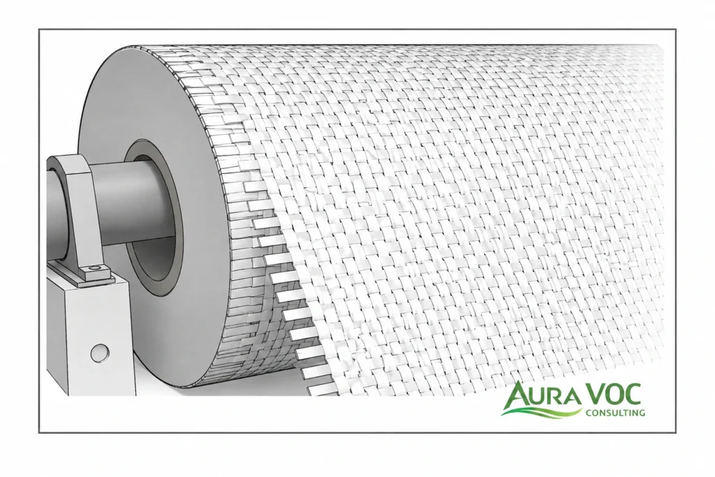
Styrene emissions control in fiberglass manufacturing is rarely solved by selecting an abatement unit alone. In many plants, the limiting factor is not the destruction capability of the technology, but the way styrene is released, captured, diluted, transported, and loaded into the treatment system.
Fiberglass and FRP production often combines open resin application, variable part geometry, intermittent gelcoat spraying, curing emissions, trimming operations, and resin-contaminated waste handling. These conditions create exhaust streams that can be difficult to stabilize. A plant may have high total airflow but relatively low styrene concentration, short VOC peaks during spraying, delayed emissions during curing, and fugitive sources that never reach the abatement unit.
For plant managers, EHS managers, and process engineers, the practical question is not simply which VOC abatement technology can remove styrene. The more useful question is what combination of capture design, airflow control, source segregation, treatment technology, and maintenance strategy can control styrene under real production conditions.
Poorly characterized styrene exhaust can lead to oversized equipment, excessive oxidizer fuel consumption, unstable capture, failed performance tests, persistent odor, or recurring maintenance problems. A regenerative thermal oxidizer, catalytic oxidizer, activated carbon system, concentrator, scrubber, or biofilter may all be technically possible in some situations. Each option has constraints related to exhaust volume, styrene loading, pressure drop, energy use, contaminant sensitivity, maintenance access, and retrofit feasibility.
Before comparing equipment, the plant needs a clear understanding of where styrene is generated, how it moves through the building, and how production variability affects the exhaust stream.
Why Styrene Emissions Are Difficult to Control in Fiberglass and FRP Manufacturing
Styrene control in fiberglass manufacturing is challenging because emissions are often distributed across several process steps rather than released from a single, well-contained source. Unlike a closed reactor vent or a solvent tank vent, many fiberglass operations involve open surfaces, manual handling, large parts, and changing work zones. This makes capture design as important as the abatement technology itself.
Two plants with similar resin consumption can have very different styrene emission profiles. Part size, resin system, application method, cure time, ventilation layout, operator work practices, and seasonal conditions all affect the exhaust conditions seen by the treatment system. Equipment selected from nominal resin usage alone can be poorly matched to the actual plant.
Main styrene sources in fiberglass production
The most visible styrene sources are resin mixing, gelcoat spraying, hand lay-up, spray-up, and open molding. These operations expose liquid resin or gelcoat to air and can generate short-duration concentration peaks, especially during spraying or high-surface-area application.
Curing areas are also important. Styrene release does not necessarily stop when resin application ends. Parts may continue to emit during gelation, early cure, demolding, trimming preparation, or temporary storage. If those parts are moved outside a controlled ventilation zone, a plant can experience odor complaints or elevated workplace readings even when the main booth or lay-up area appears to be controlled.
Additional sources can include waste resin containers, used rollers and brushes, contaminated wipes, solvent cleaning stations, open gelcoat drums, resin transfer containers, and deposits inside ducts or filters. U.S. EPA guidance for reinforced plastic composites production identifies styrene and related HAP emissions from thermoset resin and gel coat operations. These sources are often smaller individually, but they can contribute to persistent background styrene levels and make troubleshooting more difficult.
Why open molding creates high-airflow, low-concentration exhaust
Open molding is difficult to control because emissions are generated over a broad surface rather than at a compact exhaust point. To maintain acceptable capture, plants often rely on large volumes of general or booth ventilation. This can reduce local styrene concentration in the work area, but it also produces diluted exhaust that is more expensive to treat.
High airflow affects almost every part of the abatement design. Larger fans are required, duct sizes increase, oxidizers must handle more volume, and pressure drop becomes a larger operating cost. If the VOC concentration is low, an oxidizer may require more supplemental fuel because the styrene load does not contribute enough heat to support efficient operation.
In these cases, improving capture geometry or segregating exhaust streams may be more valuable than simply increasing treatment capacity. The objective is not only to move more air, but to move air in a controlled direction from the emission zone to the collection system with as little unnecessary dilution as practical.
How resin formulation, temperature, and cure profile affect styrene release
Styrene emissions are influenced by resin composition and process conditions. Resin styrene content, resin temperature, catalyst level, gel time, part thickness, surface area, and cure profile all affect how much styrene is released and when it is released.
Temperature is especially important in day-to-day operation. Warmer resin and warmer production areas can increase volatilization and change the timing of emissions. Seasonal ventilation changes can also alter capture stability. A system that performs acceptably during cooler months may show higher odor impact or higher measured concentrations during summer operation.
Formulation changes should not be treated as minor process adjustments from an emissions perspective. Switching resin suppliers, changing gelcoat, modifying catalyst dosing, or introducing additives can change VOC loading. These changes may also introduce contaminants that affect catalysts, concentrator rotors, filters, or carbon beds.
Why curing areas can remain a styrene source after application stops
Curing emissions are frequently underestimated because they are less visible than spraying or lay-up. A part may continue releasing styrene after it leaves the main application area. If curing takes place in open plant space, near doors, or in areas with weak exhaust control, emissions may bypass the main capture system.
This creates several operational problems. Odor may occur during periods when operators assume the main emission event has ended. VOC readings may not correlate neatly with spray schedules. Treating only the spray booth exhaust may leave a significant uncaptured source.
For larger parts or slower cure schedules, curing ventilation should be evaluated as its own design issue. The plant may need controlled curing zones, delayed exhaust operation, defined part storage locations, or procedures that prevent freshly laminated parts from being moved into uncontrolled areas too early.
Mapping Styrene Sources Before Sizing VOC Abatement Equipment
Abatement equipment should not be sized before the plant understands the source pattern. Styrene control projects are often weakened by incomplete source mapping: a flow rate is taken from a fan nameplate, a concentration is measured during one production condition, and the treatment unit is selected without confirming how the process behaves across shifts, products, and cleaning cycles.
A more reliable approach is to map sources by production area, measure exhaust conditions under representative operation, and identify which streams are concentrated enough to treat separately. This reduces the risk of oversizing equipment for diluted air or undersizing it for short VOC peaks.
Building an emission inventory by process area
A practical emission inventory should follow the process, not just the building layout. The inventory should include resin storage, resin mixing, gelcoat preparation, spraying, open molding, hand lay-up, curing, demolding, trimming, cleaning, and waste handling.
For each area, the plant should identify whether the source is continuous, intermittent, batch-based, or related to specific operator actions. It is also useful to distinguish between sources that are already ducted and sources that remain fugitive within the building.
This mapping often reveals that the main abatement system is treating only part of the problem. For example, a gelcoat booth may be ducted to treatment, while curing parts, waste containers, and resin handling remain outside the controlled exhaust path.
Measuring airflow, styrene concentration, and production variability
Useful design data includes actual exhaust airflow, styrene concentration range, peak values, process schedule, fan operating modes, damper positions, and production conditions during measurement. Nameplate fan capacity is not enough. Duct restrictions, filter loading, damper settings, branch imbalance, and building pressure can all affect the actual flow delivered to the abatement system.
Styrene concentration should be evaluated during normal production, peak production, idle periods, cleaning, startup, and shutdown where relevant. Measurement records should also note filter condition, fan speed, door positions, seasonal ventilation status, and whether curing parts were present during sampling.
A single average value can hide short peaks that determine carbon breakthrough, oxidizer loading, LEL safety margins, or odor impact.
Why peak styrene loads matter more than average concentration
Average concentration is useful for estimating long-term loading and operating cost, but peak concentration is often more important for system reliability. Gelcoat spraying, resin changeovers, large-part lay-up, or cleaning events can create short spikes that challenge control systems.
For carbon adsorption, peaks can accelerate breakthrough or create thermal concerns. For oxidizers, peaks influence burner control, inlet safety logic, and destruction performance. For concentrators, peaks may affect rotor loading and desorption balance. For ventilation systems, peaks can expose weaknesses in capture zones or makeup air balance.
Designing only around average concentration can lead to a system that looks acceptable on paper but struggles during real production events.
Separating concentrated sources from diluted general ventilation
Before routing all exhaust to one treatment system, plants should evaluate whether higher-load sources can be separated from diluted general ventilation. Gelcoat booths, enclosed curing areas, resin mixing stations, or localized lay-up zones may produce streams that are more suitable for direct treatment than whole-building exhaust.
Source segregation can reduce total treatment volume, improve VOC concentration, and lower fan and thermal energy demand. It can also make troubleshooting easier because each process area has a clearer relationship to the abatement system.
Segregation must still be balanced against duct complexity, access, pressure control, and operator workflow. In many fiberglass plants, the most effective control strategy begins with better source mapping and capture discipline rather than immediate replacement of the abatement unit.
Capture and Ventilation Design for Styrene Emissions from Open Molding and Gelcoat Areas
Capture design is usually the first engineering constraint in styrene emissions control. If the exhaust system does not collect the styrene released from resin application and curing, downstream abatement performance becomes secondary. An oxidizer or adsorption system can only treat the fraction of emissions that reaches the inlet.
In fiberglass plants, capture design has to account for operator movement, part size, crane or handling access, resin application method, and curing location. A technically sound layout on a drawing can perform poorly if it interferes with production or if operators need to move parts outside the controlled zone to complete the job.
Local exhaust ventilation versus general plant ventilation
General ventilation can dilute styrene concentrations in the work area, but it is usually a weak basis for efficient VOC abatement. Large volumes of diluted air increase fan power and treatment system size while providing limited control over where the emissions are captured.
Local exhaust ventilation is more effective when the release point is predictable. Examples include resin mixing stations, gelcoat booths, small lay-up tables, waste resin handling areas, or trimming stations. Slot hoods, side-draft hoods, downdraft tables, and booth exhaust can all be useful when the airflow pattern is compatible with the work process.
For large open molding operations, the challenge is that the emission source may be the entire surface of the part. In these cases, local exhaust may need to be combined with partial enclosure, controlled directional airflow, or defined work zones. The goal is to move styrene away from the operator and toward the collection system without pulling excessive clean air into the exhaust.
Enclosure strategies for open molding and curing operations
Partial enclosures often provide better control than simply increasing exhaust volume. A three-sided booth, curing tunnel, movable extraction hood, or enclosed lay-up cell can reduce cross-drafts and improve capture stability. By limiting the open area around the source, the plant can often improve VOC collection without increasing airflow in proportion to the full room volume.
For curing operations, enclosure strategy depends on part size and handling sequence. Smaller parts may be moved into a dedicated curing room or tunnel. Larger parts may require localized extraction or extended ventilation in the molding area. The practical issue is often material flow: if a part has to be moved by crane, forklift, or trolley, the enclosure must allow access without becoming permanently open during operation.
Enclosures should also be reviewed for cleaning access. Resin overspray and fiber dust can accumulate on walls, duct entries, extraction grilles, and dampers. If access is poor, the enclosure may perform well initially but degrade as deposits build up.
Makeup air, cross-drafts, and capture stability
Capture performance is strongly affected by building pressure and makeup air distribution. Open doors, roof fans, wall fans, compressed air use, seasonal ventilation changes, and nearby process exhausts can all disrupt the intended airflow path.
A common problem is a booth or hood that performs acceptably during commissioning but loses capture when doors are opened, summer ventilation fans are used, or production in adjacent areas changes. In fiberglass plants, large doors and part handling openings are especially important because they can create strong local air movement.
Makeup air should be introduced so that it supports the capture direction rather than opposing it. High-velocity supply air directed across a lay-up area can push styrene away from the exhaust point. Poorly balanced supply and exhaust can also make doors difficult to operate or cause emissions to migrate into adjacent areas.
Balancing operator exposure control with VOC abatement efficiency
Reducing exhaust volume can improve abatement economics, but it cannot be done without considering operator exposure and process access. A capture system that reduces airflow too aggressively may increase styrene concentration in the breathing zone or create stagnant areas around large parts.
The engineering target is controlled airflow, not simply low airflow. A well-designed enclosure or hood can reduce unnecessary dilution while maintaining effective capture. In contrast, closing dampers or reducing fan speed without confirming workplace conditions can create exposure and odor issues.
This balance is especially important when retrofitting existing plants. Operators may have developed work practices around the original ventilation pattern. Any change to airflow, hood position, enclosure doors, or part movement should be evaluated under real production conditions using airflow checks, smoke visualization, and workplace readings where appropriate. OSHA provides occupational exposure and sampling information for styrene that can support workplace exposure review during ventilation changes.
Duct routing and leakage before the abatement unit
Ductwork between the capture point and treatment unit is often treated as a secondary detail, but it can have a significant effect on system performance. Long duct runs, poorly balanced branches, unnecessary bends, undersized sections, and leaking connections can reduce capture and increase pressure drop.
Leaks before the abatement unit can also create misleading test results. The fan may be moving the expected total volume, but part of that volume may be clean dilution air entering through duct leakage instead of contaminated air from the process area. This reduces the measured inlet concentration and can leave fugitive emissions inside the building.
For styrene service, duct access is important. Resin mist and glass fiber dust can create sticky deposits, especially near hoods, elbows, dampers, and low-velocity sections. Access doors, cleanout points, and differential pressure monitoring should be considered during design, not added only after fouling becomes a recurring maintenance issue.
Design Data Required for Styrene VOC Abatement System Selection
Technology selection should be based on measured operating data, not only resin consumption or fan nameplate capacity. Resin use can support a mass-balance estimate, but it does not define capture efficiency, exhaust volume, styrene peaks during gelcoat spraying, or pressure drop available at existing fans.
For fiberglass plants, the most useful design basis combines process information, ventilation data, contaminant loading, and retrofit constraints. Without this, equipment can be oversized for diluted airflow, undersized for short-term VOC peaks, or poorly matched to resin mist and fiber dust conditions.
Exhaust airflow and concentration range
Actual exhaust flow should be measured at representative duct locations, preferably by branch where the system collects multiple process areas. Design drawings and fan curves are useful references, but they should be checked against real operating conditions.
Important data includes exhaust flow from gelcoat booths, lay-up areas, curing zones, mixing stations, and general ventilation; styrene concentration at normal and peak production; fan speed, damper positions, and filter condition during measurement; branch imbalance between near and remote workstations; and airflow changes when doors, roof vents, or seasonal ventilation systems are operating.
High-flow, low-concentration exhaust is common in open molding and FRP manufacturing. From an abatement standpoint, this is often the cost driver. A large airflow may require a larger oxidizer, larger ductwork, higher fan power, and more supplemental fuel, even if the actual mass of styrene is moderate.
Styrene load variability across shifts and production campaigns
Styrene loading is rarely constant across a production shift. Gelcoat spraying may create short peaks. Open lay-up may generate a more sustained release. Curing can produce a lower but longer emission tail. Cleaning, resin changeover, or waste handling can add additional VOC load outside the main production window.
The measurement plan should include gelcoat spray periods, large-part lay-up, curing after application stops, idle periods, cleaning operations, startup, shutdown, and product or resin formulation changes.
This variability affects equipment behavior. Carbon beds may break through earlier than expected if peak loading is not considered. RTOs may show high fuel use during low-load periods. Concentrators may require stable enough inlet conditions to maintain effective adsorption and desorption balance.
For intermittent production, the operating schedule is as important as the peak load. A system that runs at full exhaust and full temperature during long idle periods can have high operating cost relative to the actual styrene mass treated.
Particulate, resin mist, humidity, and temperature conditions
Styrene exhaust from fiberglass production is often not a clean vapor stream. It can contain resin aerosol, gelcoat overspray, glass fiber dust, humidity, and fine particulate. These materials influence both equipment selection and maintenance frequency.
Resin mist can foul filters, ducts, carbon beds, concentrator rotors, catalysts, and RTO media. Glass fiber dust can increase pressure drop and reduce effective airflow at remote capture points. Moisture can affect adsorption behavior, corrosion risk, and filter performance.
Before selecting abatement equipment, the plant should document whether pretreatment is required. This may include prefilters, demisters, washable filters, mist eliminators, or duct cleanout access. These components protect the abatement unit but add pressure drop and maintenance requirements.
LEL monitoring and explosion safety considerations
Many fiberglass exhaust streams are diluted, but short-term high-concentration events can still occur. These may be caused by gelcoat spraying, resin spills, cleaning, poor ventilation balance, or abnormal damper positions.
The design should account for lower explosive limit safety margins, inlet concentration monitoring, airflow interlocks, purge sequences, fan failure response, burner permissives for oxidizers, bypass and shutdown logic, and abnormal operating scenarios.
LEL monitoring should not be used as a substitute for proper capture and ventilation design. It is a safety layer, not the primary control strategy.
Retrofit constraints in existing fiberglass plants
Most fiberglass VOC projects are retrofits, and practical layout constraints often shape the final design. A centralized oxidizer may be technically suitable but difficult to install if duct routing crosses crane paths, requires long negative-pressure duct runs, interferes with forklift traffic, or leaves inadequate access for fan, filter, media, or carbon replacement.
Key retrofit constraints include available outdoor or indoor equipment space, duct routing from booths and curing zones, roof penetrations, structural support, gas and electrical capacity, access for maintenance, production downtime during installation, existing fan capacity, available static pressure, and safe access to sampling ports and instrumentation.
These constraints should be reviewed before requesting equipment proposals. Otherwise, vendors may size technically plausible systems that are difficult to install, maintain, or operate in the actual plant.
Abatement Technologies for Styrene Exhaust from Fiberglass Manufacturing
Once source mapping and capture data are available, the abatement technology can be evaluated against the actual exhaust stream. The decision should not be based only on destruction efficiency. For fiberglass applications, the relevant questions are whether the system can handle diluted airflow, tolerate resin mist and fiber dust, manage production peaks, and remain maintainable under site conditions.
Regenerative thermal oxidizers for styrene emissions
Regenerative thermal oxidizers are often considered for styrene emissions where the exhaust flow is substantial and production is relatively continuous. Their advantage is robust VOC destruction with heat recovery through ceramic media.
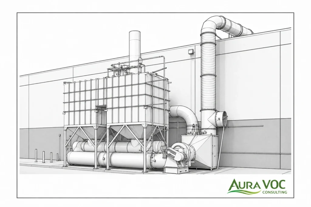
For fiberglass exhaust, the main concern is fuel demand. If the inlet styrene concentration is low because of high dilution airflow, the VOC load may not provide enough heat contribution to reduce burner firing. The oxidizer may then operate mainly as a large air heater. Idle operation, frequent startups, purge cycles, and low production periods can further increase gas consumption.
Practical checks before selecting an RTO include actual exhaust airflow, styrene concentration during spray peaks and normal operation, operating hours per week, expected idle or standby periods, resin mist and particulate loading, available fan pressure, access for media inspection and replacement, and the ability to isolate or reduce airflow during non-production periods.
RTO media can plug or foul if resin aerosol and fiber dust reach the unit. Upstream filtration and demisting should be evaluated as part of the RTO design, not as optional accessories.
Catalytic oxidation for styrene VOC control
Catalytic oxidation can reduce operating temperature compared with thermal oxidation, which may reduce fuel use where inlet conditions are suitable. The tradeoff is catalyst sensitivity.
In fiberglass service, catalyst life depends heavily on inlet cleanliness and material compatibility. Resin aerosols, glass fiber dust, silicones, phosphorus compounds, sulfur compounds, halogenated materials, and some cleaning products can foul or poison the catalyst. If these materials are present, the system may lose activity or develop increased pressure drop before the expected service interval.
Catalytic oxidation should be evaluated with attention to upstream filtration performance, resin and gelcoat formulation, cleaning chemicals used in the area, aerosol carryover, catalyst bed differential pressure, catalyst activity testing, bypass prevention, and temperature control.
It can be suitable where the exhaust is well-filtered and process materials are compatible, but it is less forgiving than thermal oxidation when contaminants are poorly controlled.
Activated carbon adsorption for intermittent styrene sources
Activated carbon can be practical for lower-flow or intermittent styrene sources, such as small booths, resin mixing stations, waste handling vents, or production areas with limited operating hours. Its main advantage is that it avoids continuous thermal energy demand.
The operating burden shifts to media management. Carbon beds require breakthrough monitoring, temperature checks, pressure drop tracking, and defined replacement criteria. Inlet temperature and humidity can affect adsorption capacity. Resin mist and particulate can plug the bed or create uneven loading if pretreatment is weak.
Important design and operating checks include expected styrene mass loading per shift, peak inlet concentration, breakthrough curve and sampling frequency, bed temperature monitoring, inlet filtration, pressure drop baseline after new carbon installation, safe storage and disposal of spent carbon, and a contingency plan during carbon changeout.
Carbon should not be treated as a passive box in the duct. It remains effective only if the plant monitors outlet concentration and replaces or regenerates media before breakthrough becomes a compliance or odor issue.
Zeolite concentrators for high-flow, low-concentration styrene exhaust
Zeolite concentrators can be useful when the plant has high-volume, low-concentration VOC exhaust. The concentrator adsorbs VOCs from the main exhaust stream and desorbs them into a smaller, more concentrated stream for downstream oxidation.
This can reduce oxidizer size and fuel demand, but it adds mechanical and control complexity. The rotor must be protected from resin mist, fiber dust, and incompatible compounds. Seal leakage, rotor fouling, desorption temperature control, and pressure drop all affect performance.
A concentrator is more likely to be practical when exhaust airflow is high, styrene concentration is relatively low, operation is frequent enough to justify the added equipment, inlet air can be filtered effectively, the downstream oxidizer is correctly matched to the desorption stream, and maintenance staff can manage rotor inspection, seals, filters, and controls.
For heavily contaminated or highly intermittent exhaust, the additional complexity may outweigh the energy benefit.
Wet scrubbers and limitations for styrene control
Wet scrubbers are usually limited as a primary control technology for vapor-phase styrene because styrene has low water solubility. A scrubber may remove aerosols, particulate, or soluble co-contaminants, but it should not be assumed to provide strong styrene vapor removal without a specific design basis.
Chemical additives may improve removal in some cases, but they introduce other issues: blowdown, wastewater treatment, chemical handling, corrosion, solids management, and mist eliminator fouling. For fiberglass plants, this can move part of the problem from air treatment to wastewater and secondary waste management. The European Commission STS BREF provides broader BAT context for solvent-using processes, including emissions to air and water and cross-media effects.
Wet systems may have a role as pretreatment where aerosol removal is needed, but they are rarely the main solution for styrene vapor control.
Biofiltration for low-concentration continuous VOC streams
Biofiltration may be considered for low-concentration, continuous exhaust where footprint is available and inlet conditions are stable. The system depends on biological activity, so humidity, temperature, residence time, nutrient balance, and loading stability matter.
For fiberglass plants with intermittent production, VOC peaks, shutdowns, resin mist, or limited space, biofiltration can be difficult to operate consistently. It should be considered only after confirming that the exhaust is stable enough and that the plant can maintain the required operating conditions.
Engineering Tradeoffs in Styrene Emissions Control
Styrene control decisions usually involve tradeoffs between capture, airflow, energy, pressure drop, contamination risk, and maintenance effort. The lowest capital cost option is not always the lowest operating cost option, and the most efficient abatement unit may still perform poorly if capture is unstable.
Capture efficiency versus exhaust airflow
Increasing airflow can improve local capture, but it may also dilute the exhaust and increase treatment cost. For example, increasing booth exhaust to address odor may reduce styrene concentration at the oxidizer inlet, increasing supplemental fuel demand while leaving curing emissions outside the booth unchanged.
The better approach is usually to improve capture geometry first: enclosures, hood position, airflow direction, and makeup air distribution. More airflow should be added only where it improves capture under real working conditions.
RTO fuel demand versus airflow dilution
RTO fuel demand is strongly influenced by exhaust volume and VOC concentration. A diluted styrene stream may require continuous burner firing because the VOC load does not provide enough heat input. This becomes more important during idle periods, low production days, or operations with long ventilation hours and short resin application periods.
Before selecting or resizing an RTO, the plant should check whether airflow can be reduced through zoning, source segregation, VFD control, or standby modes without weakening capture or worker exposure control.
Carbon adsorption simplicity versus breakthrough and waste management
Carbon adsorption may appear simpler than oxidation, but the operating risk is breakthrough. If the outlet is not monitored or the replacement interval is based only on calendar time, the bed can become ineffective while airflow and pressure readings still appear normal.
Carbon also creates secondary waste and handling requirements. For styrene service, bed temperature, outlet sampling, pressure drop trend review, and fire-safe changeout procedures should be part of the operating plan.
Concentrator efficiency versus added complexity
A concentrator can reduce the air volume sent to oxidation, but it introduces rotor protection, desorption heating, seal maintenance, additional controls, and extra pressure drop. It is not simply an energy-saving device; it is a more complex process unit.
The decision should compare the fuel savings from concentrating the stream against the maintenance burden, filtration requirements, downtime risk, and controls capability at the site.
Catalytic oxidation energy savings versus catalyst fouling risk
Catalytic oxidation can reduce fuel consumption where the exhaust is clean enough for stable catalyst performance. In fiberglass manufacturing, this benefit must be weighed against the risk of catalyst fouling from resin mist, particulate, or incompatible process materials.
If inlet protection is weak, the plant may save energy initially but lose performance as catalyst activity declines or pressure drop increases.
Airflow reduction versus worker exposure and process access
Airflow reduction is often attractive because it lowers fan power and treatment volume. However, reducing airflow without confirming capture can increase operator exposure or allow styrene to migrate into adjacent areas.
Any airflow reduction should be validated with smoke visualization, branch flow measurements, workplace readings, and observation during normal operator movement. The control system has to fit the work process, not only the calculation.
Pressure Drop, Fan Power, and Thermal Energy Implications
Pressure drop should be treated as an operating variable, not only a design value. In fiberglass exhaust systems, pressure drop changes as filters load, resin deposits accumulate, dampers shift, and duct branches become contaminated.
Where pressure drop occurs in fiberglass VOC exhaust systems
Pressure losses occur across hoods, duct entries, elbows, branch dampers, filters, demisters, carbon beds, concentrator rotors, oxidizer media, fans, and stacks. A useful system review separates pressure drop by component rather than looking only at total fan static pressure.
This matters because the same total pressure drop can have different causes. A loaded prefilter, a plugged duct branch, and fouled RTO media may create similar symptoms but require different corrective action.
How resin mist and glass fiber dust increase system resistance
Resin mist creates sticky deposits that collect dust and fibers. Glass fiber dust can load filters, settle in low-velocity duct sections, and foul dampers or grilles. Over time, the system may lose airflow at the remote or highest-resistance branches first.
A common symptom is uneven capture: workstations closest to the fan still perform acceptably, while distant hoods lose effectiveness. If only total fan operation is checked, the problem can be missed.
Fan energy impact of high-volume exhaust systems
Fan energy increases with airflow and pressure requirement. In high-volume fiberglass ventilation systems, even moderate increases in pressure drop can create noticeable electrical demand or force the fan to operate away from its intended point.
A pressure drop review should include the current operating point on the fan curve, filter and demister differential pressure, branch airflow balance, duct velocity in critical sections, damper positions, fan belt and bearing condition, and evidence of resin deposits on fan components.
If the fan compensates through higher speed or damper adjustment, energy use may increase while capture still deteriorates in parts of the system.
Thermal energy demand in RTOs and oxidizers
Thermal oxidizer energy demand depends on airflow, inlet temperature, styrene concentration, heat recovery, purge operation, and idle mode. Low-concentration styrene exhaust may not reach self-sustaining operation, especially when the exhaust stream is highly diluted.
Plants should review oxidizer temperature trends against production activity. High fuel use during low production may indicate excessive ventilation hours, air leakage, poor standby control, valve leakage, or heat recovery deterioration.
Practical methods to reduce energy use without weakening capture
Energy reduction should start with airflow control and source segregation, not arbitrary damper closure. Practical measures include separating high-load sources from general ventilation, using VFD control tied to production modes, improving enclosure geometry, sealing duct leakage, reducing unnecessary exhaust during idle periods, and maintaining filters and demisters before pressure drop becomes excessive.
The final check should always be operational: the system must still capture styrene during actual spraying, lay-up, curing, cleaning, and part movement.
Maintenance Issues Caused by Resin Mist, Glass Fiber Dust, and Styrene Exhaust
Maintenance reliability is central to styrene control. Fiberglass exhaust systems often degrade gradually rather than fail suddenly. A system may continue running while capture efficiency, energy use, or outlet VOC performance worsens.
Prefilter and demister maintenance
Prefilters and demisters protect downstream equipment from resin aerosols and fiber dust. Their differential pressure should be trended, not only checked when an alarm occurs. A useful baseline should be recorded after filter replacement or cleaning, then compared against operating values.
Initial inspections after commissioning or process changes should be more frequent because loading rates are often uncertain. Once the plant understands the loading pattern, inspection intervals can be adjusted based on pressure drop trends and visual condition.
Duct cleaning and resin buildup
Duct deposits are common near hoods, elbows, dampers, low-velocity sections, and branch transitions. Sticky deposits can reduce cross-sectional area, create odor sources, increase fire risk, and make airflow balancing unstable.
Ductwork should include cleanout access at likely accumulation points. If access is poor, maintenance tends to shift from planned cleaning to reactive shutdowns after capture deteriorates.
Carbon bed monitoring and replacement planning
For carbon systems, maintenance should be based on measured performance. Outlet VOC concentration, bed temperature, and differential pressure should be reviewed together. A normal pressure drop does not prove the carbon is still adsorbing styrene.
Replacement planning should consider production schedule, safe isolation, temporary emission control during changeout, spent carbon storage, and disposal requirements. Carbon changeout should not depend only on a fixed calendar interval unless operating load is very stable.
RTO media, valves, burners, and insulation
RTO maintenance should include ceramic media condition, valve sealing, burner tuning, insulation, temperature distribution, and pressure drop across the unit. Media plugging can increase fan load and reduce heat recovery. Valve leakage can reduce destruction performance and increase fuel use.
Temperature trends should be compared with production activity. A system requiring more fuel than expected may have airflow dilution, heat recovery deterioration, valve leakage, or poor operating mode control.
Catalyst protection and deactivation risks
Catalysts should be monitored for both activity loss and pressure drop increase. If outlet VOC rises, the cause may be fouling or poisoning rather than insufficient temperature alone.
The plant should review resin formulations, additives, cleaning chemicals, and aerosol carryover when catalyst performance changes. Replacing catalyst without addressing the upstream cause may only repeat the failure.
Instrumentation and control system checks
VOC monitors, LEL sensors, pressure transmitters, temperature probes, dampers, and interlocks need periodic calibration and functional testing. Instrument drift can lead operators to adjust the system incorrectly.
Sampling ports and pressure taps should remain accessible and clean. In contaminated fiberglass exhaust, blocked pressure taps or dirty probes can produce misleading readings.
Troubleshooting Styrene Odor, High VOC Readings, and Poor Capture Performance
Troubleshooting should start by separating three questions: Is styrene being generated where expected? Is it being captured? Is the captured stream being treated correctly? Jumping directly to the abatement unit can miss common upstream problems.
Persistent styrene odor after abatement installation
Persistent odor often means part of the styrene load is not reaching the abatement unit.
Likely causes include curing parts stored outside controlled ventilation, open waste resin containers, duct leakage before the treatment unit, bypass dampers left open, poor capture at large open surfaces, emissions from cleanup areas, or unfavorable stack discharge and building re-entrainment.
Useful checks include smoke visualization near lay-up and curing zones, handheld VOC screening around waste areas, duct leakage inspection, damper position verification, and review of part movement after lay-up.
High outlet VOC concentration
High outlet VOC means the treatment step itself should be checked, but the inlet condition must be reviewed first.
For oxidizers, compare outlet readings with combustion chamber temperature, residence time, airflow, and inlet concentration peaks. For carbon, check for breakthrough using outlet sampling and review bed temperature. For catalytic systems, review catalyst activity, pressure drop, and possible fouling. For concentrators, check rotor rotation, desorption temperature, seals, and downstream oxidizer performance.
A short VOC spike during gelcoat spraying can produce different diagnostic conclusions than a sustained outlet increase during normal operation.
Rising pressure drop across the exhaust system
Rising pressure drop should be localized by component. Checking only total system pressure can hide the cause.
Possible causes include loaded filters, resin mist on demisters, glass fiber dust in duct branches, sticky deposits at elbows, fouled dampers, wet deposits or condensate, carbon bed loading, plugged RTO media, or a fouled concentrator rotor.
Branch airflow measurements are useful because pressure drop problems often appear first as poor capture at remote hoods.
Excessive oxidizer fuel consumption
High fuel consumption can result from low styrene concentration, excess dilution air, poor heat recovery, air leakage, long idle operation, or control modes that keep the unit at full temperature when production is low.
Operational checks should include inlet VOC trends, exhaust flow, production schedule, purge settings, standby mode, burner firing trends, valve leakage, and heat recovery condition. If fuel use increased after a ventilation change, the issue may be airflow dilution rather than oxidizer failure.
Uneven capture across workstations
Uneven capture usually points to airflow distribution rather than treatment efficiency. Common causes include branch imbalance, blocked duct sections, poor hood position, cross-drafts, makeup air interference, open doors, or operator work practices that move the emission source away from the capture zone.
Checks should be done during real production, not only during an empty-booth inspection. Operator movement, part size, crane access, and open enclosure doors can all change capture performance.
VOC spikes during spraying, gelcoat, or cleaning operations
VOC spikes should be correlated with production events. Gelcoat spraying, resin mixing, cleaning, and waste handling may require separate capture or control logic if they dominate peak load.
If spikes are short but high, the system may need improved source capture, production sequencing, carbon capacity adjustment, oxidizer control review, or separation of peak sources from general ventilation.
Wastewater and Secondary Waste from Styrene Control Systems
Styrene air control can create secondary waste streams that need to be considered during technology selection and maintenance planning. These issues are not always large enough to determine the technology choice, but they can affect operating procedures, disposal cost, and plant housekeeping.
Why wet scrubbing can create wastewater obligations
Wet systems may require additives or generate blowdown. Because styrene is not easily removed by water alone, wastewater may become a complication without solving the primary vapor-phase control problem.
Scrubber blowdown may contain organics, suspended solids, chemical additives, resin residues, and other co-contaminants. Mist eliminators can also foul if resin aerosol is present, increasing pressure drop and maintenance frequency.
Washdown water from ducts, demisters, and filters
Cleaning resin-laden ducts, demisters, filters, and collection surfaces can produce contaminated washwater. The plant should define how this water will be collected, stored, characterized, and disposed of before maintenance begins.
If cleaning is performed without containment planning, the air control system can create an unplanned wastewater or sludge-handling issue.
Spent activated carbon and contaminated filters
Spent carbon, loaded filters, and demister media may contain styrene, resin residues, or other VOCs. Storage, fire-safe handling, replacement frequency, disposal classification, and transport requirements should be included in the operating procedure.
For carbon systems, waste management is part of the abatement cost. A system that looks simple mechanically can still require disciplined media logistics.
Resin-contaminated waste handling and fugitive emissions
Open resin drums, used wipes, sludge, gelcoat residues, and contaminated tools can contribute to background odor. These sources can also confuse troubleshooting because they may create styrene readings unrelated to the main ducted exhaust system.
Housekeeping should be reviewed alongside engineered controls. Covered containers, designated waste areas, prompt removal of resin waste, and controlled cleaning stations can reduce fugitive emissions that are otherwise difficult to capture.
Process Changes That Reduce Styrene Load Before Abatement
Process-level changes can reduce the load entering the ventilation system, but they should be assessed against product quality, cycle time, tooling, and operator workflow. They are not substitutes for capture where significant emissions remain.
Low-styrene and low-emission resin systems
Low-styrene or low-emission resin systems can reduce emissions, but they may change gel time, cure profile, viscosity, surface finish, laminate properties, and operator handling. A plant trial should confirm product quality, production rate, and downstream finishing requirements before assuming a direct substitution is practical.
Resin changes should also be reviewed for effects on abatement equipment. Additives, inhibitors, fillers, or cleaning requirements may affect filtration, catalyst compatibility, or carbon performance.
Closed molding, infusion, and process conversion options
Closed molding and infusion can reduce open-surface emissions, but they involve tooling investment, process development, operator training, and possible changes in cycle time. These options are more practical for repeatable parts than for highly variable or large custom components.
The emission reduction benefit should be compared with capital cost, production flexibility, training requirements, and reject risk during process transition.
Improved spray application and gelcoat control
Spray settings and operator technique affect both styrene release and particulate loading. Better transfer efficiency can reduce overspray, filter loading, resin deposits, and cleaning frequency.
For gelcoat booths, the plant should review spray pressure, gun setup, part positioning, booth airflow, and cleaning practices. Small process changes can reduce peak VOC loading and maintenance burden.
Material handling and housekeeping controls
Closed containers, covered waste bins, prompt removal of resin waste, controlled resin temperature, and defined cleaning areas can reduce fugitive styrene sources. These measures are especially important when troubleshooting odor because open waste containers or contaminated wipes can distort the apparent performance of the engineered capture system.
Housekeeping does not replace ventilation or abatement, but poor housekeeping can make a good system appear ineffective.
Practical Selection Framework for Styrene Emissions Control
A practical selection process should connect measurement data to equipment decisions. The objective is to determine whether the limiting factor is source capture, airflow volume, contaminant loading, abatement technology, or maintenance condition.
Step 1 — Define styrene sources and capture requirements
Identify all release points: gelcoat spraying, open molding, resin mixing, curing, trimming, cleaning, and waste handling. Separate sources that are already ducted from those that remain fugitive.
This step determines whether the project is mainly a capture problem, an abatement problem, or both.
Step 2 — Measure airflow and VOC concentration under real production conditions
Measure actual airflow and styrene concentration during representative conditions, including spray peaks, lay-up, curing, idle periods, and cleaning. Record damper positions, fan speed, filter condition, and production activity during testing.
This data informs system sizing, peak-load handling, fuel demand, carbon capacity, and LEL safety margins.
Step 3 — Identify contaminants that affect treatment equipment
Document resin mist, glass fiber dust, gelcoat overspray, humidity, cleaning solvents, silicone-containing materials, and other additives. Review whether pretreatment is required.
This step affects the suitability of carbon, catalytic oxidation, concentrators, RTO media protection, and maintenance frequency.
Step 4 — Separate high-load sources from diluted ventilation where possible
Evaluate whether gelcoat booths, curing zones, mixing stations, or waste handling vents can be treated separately from general ventilation.
This can determine whether airflow can be reduced, concentration improved, fan power lowered, or treatment equipment downsized.
Step 5 — Compare abatement technologies by operating cost, maintenance load, and retrofit constraints
Compare RTOs, catalytic oxidizers, carbon adsorption, concentrators, scrubbers, and biofilters using the actual design basis. Include fuel, electricity, media replacement, filtration, pressure drop, downtime, access, and secondary waste.
The comparison should focus on technology feasibility under real plant operation, not only theoretical VOC removal capability.
Step 6 — Validate the selected approach with measurements and operating scenarios
Check the preferred option against peak production, seasonal ventilation, idle periods, maintenance conditions, abnormal events, and future process changes.
This validation determines whether the selected system has enough operating margin without being oversized, energy intensive, or difficult to maintain.
Example Styrene Control Scenarios in Fiberglass Plants
High-airflow, low-concentration exhaust from open molding
A plant with large open molding areas may have high exhaust volume but low styrene concentration at the treatment inlet. The symptoms are often high fan power, high oxidizer fuel use, and limited relationship between resin usage and abatement efficiency.
Likely checks include airflow measurement by branch, smoke visualization around open molds, review of makeup air direction, and comparison of styrene concentration in local zones versus main ductwork.
Possible responses include partial enclosure, improved hood geometry, source segregation, VFD control, or a concentrator review before increasing oxidizer size.
Intermittent gelcoat booth emissions with VOC peaks
Gelcoat operations can create short high-concentration peaks followed by lower emissions during flash-off and cleanup. If the system is designed only around average concentration, it may struggle during spraying.
Useful checks include time-based VOC monitoring during booth startup, spraying, flash-off, cleaning, and idle periods. The plant should also verify booth airflow and operator spray practices.
Possible responses include separate booth exhaust control, carbon sizing for peaks, oxidizer control review, or routing gelcoat exhaust separately from diluted plant ventilation.
Curing area emissions causing odor outside production hours
If odor occurs after spraying has stopped, curing emissions should be investigated. Parts may continue releasing styrene after application and may be moved to areas without adequate exhaust.
Checks include VOC screening around part storage, review of exhaust shutdown timing, observation of part movement, and comparison of odor events with curing schedules.
Possible responses include controlled curing zones, delayed ventilation shutdown, curing tunnels, revised part storage procedures, or dedicated capture for curing areas.
Existing abatement system with rising pressure drop
Rising pressure drop can reduce capture and increase fan energy before the abatement unit visibly fails.
Checks should include filter and demister differential pressure, duct inspection at elbows and low-velocity sections, branch airflow testing, fan condition, carbon bed resistance, and RTO media pressure drop.
Possible responses include revised filter maintenance, duct cleaning access, improved mist removal, fan balancing, or media inspection.
Retrofit project limited by space, duct routing, or energy cost
In existing plants, the best theoretical technology may not fit the layout. Long duct runs, crane paths, roof loading, utility limits, and maintenance access can make a centralized system impractical.
The project should compare centralized treatment with zoned treatment, phased installation, local source capture, or airflow reduction before final equipment selection.
FAQ: Styrene Emissions Control in Fiberglass Manufacturing
What is the main challenge in controlling styrene emissions from fiberglass manufacturing?
The main challenge is the combination of diffuse emissions, high ventilation volume, variable styrene concentration, and curing emissions that may occur outside the main application area.
Is an RTO suitable for low-concentration styrene exhaust?
An RTO can be suitable, but low-concentration exhaust may require significant supplemental fuel. The plant should first review airflow reduction, source segregation, operating schedule, and heat recovery condition.
When is activated carbon practical for styrene emissions?
Activated carbon is most practical for lower-flow or intermittent sources where breakthrough monitoring, bed temperature control, pressure drop tracking, and planned media replacement can be managed reliably.
Can curing areas cause styrene odor even after spraying has stopped?
Yes. Freshly laminated parts can continue releasing styrene during cure and early storage. If they are moved outside controlled ventilation zones, odor may persist after the main spray or lay-up operation ends.
Why does styrene odor persist after installing an abatement system?
Persistent odor often indicates uncaptured sources, curing emissions outside the exhaust zone, duct leakage, bypass dampers, open waste containers, cleanup sources, or poor stack discharge conditions.
How does resin mist affect VOC abatement equipment?
Resin mist can foul filters, ducts, carbon beds, concentrator rotors, catalysts, and RTO media. This can increase pressure drop, reduce airflow, shorten media life, and create maintenance problems.
What causes high pressure drop in fiberglass VOC exhaust systems?
Common causes include loaded filters, fouled demisters, resin buildup in ducts, glass fiber dust accumulation, wet deposits, carbon bed resistance, fouled dampers, or plugged oxidizer media.
Why is wet scrubbing usually limited for styrene control?
Styrene has limited water solubility, so conventional wet scrubbing is usually not effective as the primary control method for vapor-phase styrene. Scrubbers may still be useful for aerosols or specific co-contaminants.
What data is needed before selecting a styrene abatement system?
Key data includes actual exhaust airflow, styrene concentration range, peak loading, process schedule, capture layout, contaminant loading, pressure drop, fan capacity, utility availability, and retrofit constraints.
Can reducing exhaust airflow lower abatement operating cost?
Yes, if capture remains effective. Airflow reduction can reduce fan power, oxidizer size, and fuel demand, but it should be validated with airflow measurements, smoke testing, and workplace exposure review.
Should gelcoat, lay-up, and curing exhaust streams be treated separately?
Sometimes. Separate routing can improve concentration, reduce total treatment volume, simplify troubleshooting, and reduce energy use. The decision depends on layout, flow rates, source strength, and retrofit feasibility.
What maintenance indicators suggest a styrene control system is underperforming?
Warning signs include rising pressure drop, outlet VOC increase, higher oxidizer fuel use, abnormal temperatures, odor complaints, uneven capture, frequent alarms, and shorter carbon or filter life.
What is the difference between styrene capture efficiency and destruction efficiency?
Capture efficiency describes how much styrene released by the process reaches the exhaust system. Destruction efficiency describes how much captured styrene is destroyed by the abatement unit. A high-destruction oxidizer will not solve uncaptured emissions.
Why is my RTO using too much fuel on styrene exhaust?
Common reasons include excessive dilution airflow, low inlet VOC concentration, long idle operation, air leakage, poor heat recovery, valve leakage, or control modes that do not match the production schedule.
How should styrene emissions be measured before selecting abatement equipment?
Measurements should include exhaust airflow, inlet VOC concentration, peak events, curing periods, idle conditions, cleaning operations, branch flow balance, filter condition, damper positions, and production activity during sampling.
Conclusion
Styrene emissions control in fiberglass manufacturing should be evaluated as a combined process, capture, ventilation, and abatement problem. The abatement unit is only one part of the control chain. If styrene is released outside the capture zone, diluted by excessive airflow, or carried with resin mist and fiber dust, equipment performance and operating cost can differ significantly from the design expectation.
The most useful engineering review starts with measured exhaust flow, styrene concentration range, peak production events, curing emissions, duct layout, pressure drop, contaminant loading, and maintenance condition. These inputs determine whether the practical issue is capture instability, excessive dilution, poor source segregation, unsuitable technology, or maintenance-related performance loss.
For new projects, this approach reduces the risk of selecting equipment that is too large, too energy intensive, or difficult to maintain. For existing systems, it helps separate abatement failure from upstream capture, airflow, duct leakage, or production changes.
A reliable styrene control strategy should be checked against real plant operation: spraying, lay-up, curing, cleaning, idle periods, seasonal ventilation, and maintenance access. That operating perspective is usually what determines whether the system remains effective after commissioning.
CTA: Technical Review of Styrene Emissions Control
For fiberglass or FRP plants evaluating styrene emissions control, the first step is to review the operating basis: exhaust flow, styrene concentration range, source locations, capture layout, pressure drop, production schedule, resin mist loading, and existing abatement performance.
AuraVOC can review measured exhaust data, duct layout, VOC readings, pressure drop trends, and operating conditions to identify whether the limiting factor is capture, airflow balance, abatement technology, maintenance condition, or retrofit constraint.