
Benzene Emissions from Process Vents: Engineering Considerations for Industrial VOC Control
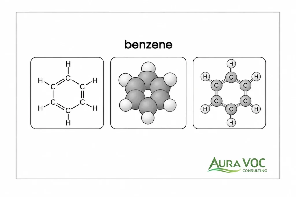
Benzene process vents are usually linked to specific operating steps: solvent charging, reaction venting, distillation, vacuum operation, condensation, solvent recovery, or wastewater handling. For this reason, benzene control should not be treated as a standalone stack issue. The vent source, batch sequence, vapor composition, pressure constraints, and downstream liquid handling route all affect whether a control strategy will work reliably in production.
In many facilities, benzene is not the dominant VOC by mass. It may appear as a raw material, impurity, recovered solvent component, or by-product. That creates a practical design problem: total VOC data may look acceptable while benzene-specific behavior remains uncertain. A vent stream dominated by other solvents can still require benzene speciation, especially where carbon breakthrough, condenser performance, worker exposure concerns, or control-device verification are involved.
For plant managers, EHS managers, and process engineers, the key question is not whether benzene can be removed in principle. The question is whether the selected control system can handle real operating conditions: peak loads, moisture, condensables, LEL limits, fan capacity, backpressure, startup and shutdown behavior, media changeout, control-device trips, and benzene-containing liquid waste. A useful evaluation starts with measured vent behavior and ends with defined operating limits that plant personnel can monitor and maintain.
Where Benzene Emissions Occur in Industrial Process Vent Systems
Benzene emissions can originate from several process areas, and the source profile often determines the appropriate control strategy. A steady vent from a storage or recovery system behaves differently from a short-duration peak during batch charging or vacuum pull-down. The same benzene mass flow can create different engineering problems depending on whether it appears as a dilute continuous stream, a concentrated intermittent release, or a condensable vapor mixed with other organics.
The first step is therefore not technology selection. It is source identification and operating-mode definition. Without that, the plant risks oversizing the wrong equipment, undersizing the critical component, or creating a control system that works during normal operation but fails during startup, cleaning, changeover, or peak vapor release.
Common Benzene-Containing Vent Sources
Common benzene-containing process vent sources include reactor vents, distillation overhead vents, condenser outlets, vacuum pump exhaust, solvent recovery systems, storage tanks, day tanks, batch charging points, and transfer operations. In some facilities, wastewater tanks, solvent-contaminated drains, oil-water separators, or equalization tanks may also act as secondary benzene emission points.
Reactor vents can release benzene during charging, heating, agitation, pressure control, or inert gas sweeping. Distillation vents may carry benzene when it is part of the overhead fraction, present as a light impurity, or stripped during solvent recovery. Condenser outlets are especially important because they represent what remains after partial vapor recovery. If condenser performance is limited by cooling-water temperature, fouling, high non-condensable flow, or insufficient residence time, the downstream vent load can be materially higher than expected.
Vacuum systems require particular attention. Liquid ring pumps, dry vacuum pumps, ejectors, and vacuum receivers can discharge benzene-containing vapors depending on process temperature, solvent volatility, leakage air, and seal-liquid management. In batch plants, vacuum pump exhaust may produce short peaks that are missed by average daily calculations but still dominate abatement design.
Storage and day tank vents can also be relevant, especially where benzene-containing solvent mixtures are charged, transferred, heated, or displaced by nitrogen blanketing. Even when individual tanks have low emissions, multiple small vents routed to a common header can create a more complex control problem due to variable flow, changing vapor composition, and header pressure effects.
Benzene as Raw Material, Impurity, Solvent Component or By-Product
Benzene does not need to be the main solvent in the process to become an abatement design concern. It may enter the plant as a raw material, exist as an impurity in hydrocarbon feedstocks, appear as a minor component in recovered solvents, or form as a by-product in specific reaction pathways. In coatings, chemical, pharmaceutical, and specialty manufacturing environments, this distinction matters because the plant may not recognize benzene as the primary VOC driver until compound-specific analysis is performed.
From an engineering standpoint, trace or variable benzene content can be difficult to manage because it may not follow the same pattern as the bulk VOC load. A total VOC analyzer may indicate stable emissions while the benzene fraction varies with raw material lot, solvent recovery efficiency, distillation cut point, reaction conversion, or campaign change. This is especially relevant in multiproduct facilities where the same vent header or abatement unit serves several production lines.
The presence of benzene as an impurity also affects maintenance and waste handling. Condensate from a vent condenser, spent activated carbon, scrubber liquid, or vacuum pump seal liquid may need to be handled based on its benzene content, not only its total organic load. If this is not considered during design, the abatement system can transfer the issue from air emissions into a liquid waste stream that still requires controlled storage, treatment, or disposal.
Continuous, Intermittent and Batch Peak Emissions
The operating pattern of the vent is one of the most important design inputs. Continuous vents can often be characterized by stable flow, temperature, and composition ranges. Intermittent and batch vents require a different approach because peak conditions may drive control device sizing, safety interlocks, and monitoring strategy.
In batch manufacturing, benzene emissions may occur during solvent charging, reactor heat-up, distillation, vacuum pull-down, pressure equalization, nitrogen purging, centrifuge unloading, filter drying, or cleaning. These events may last minutes rather than hours, but they can produce concentrated vapor releases. If sampling only captures average operation, the resulting design basis may understate the true inlet load to a carbon bed, oxidizer, condenser, or vent header.
Startup, shutdown, and solvent changeover conditions should also be reviewed. A control device may perform adequately during steady operation but experience high inlet concentration, low flow, oxygen variation, or condensate carryover during transient phases. For oxidizers, this can affect temperature stability and LEL management. For carbon beds, it can accelerate breakthrough or create localized heat generation. For condensers, it can cause overload if the cooling system cannot respond to rapid vapor release.
Why Benzene Process Vents Require Compound-Specific Evaluation
Benzene-containing process vents should not be evaluated only through total VOC concentration or total hydrocarbon readings. Those measurements are useful for screening and trend monitoring, but they do not show how much benzene is present, when it peaks, or how it behaves through the control system. For occupational exposure context, OSHA provides benzene-specific exposure limits that should be considered separately from total VOC readings.
This matters during both design and troubleshooting. A carbon bed may appear correctly sized based on total VOC mass but break through earlier than expected because of humidity, competing solvents, elevated bed temperature, or short high-concentration benzene peaks. A condenser may reduce the bulk solvent load but leave a higher-than-expected benzene concentration in the non-condensed vent gas. An oxidizer may operate within its normal temperature range while still requiring benzene-specific confirmation during performance testing.
Difference Between Total VOC and Benzene-Specific Emissions
Total VOC data describes the combined organic load. It does not identify the compound mix. In practical terms, this means a vent dominated by ethanol, IPA, acetone, toluene, heptane, or another solvent may mask a lower benzene concentration that is still important for design or compliance.
The distinction is important because each compound behaves differently. In carbon adsorption, VOCs compete for adsorption sites, and more strongly adsorbed compounds can change the effective benzene capacity. In condensation, benzene removal depends on partial pressure, cooling temperature, total non-condensable flow, and vapor-liquid equilibrium. In oxidation systems, total heating value affects fuel demand and temperature stability, while benzene destruction must still be confirmed under the relevant operating conditions.
For engineering evaluation, benzene-specific data helps identify which unit operation is responsible. If benzene peaks occur during an early distillation cut, vacuum pull-down, nitrogen purge, or solvent recovery step, the plant may be able to reduce the load upstream. Without speciation, the vent may simply appear as a general VOC source, and the opportunity to correct the process-side driver can be missed.
When Speciated Sampling Is Needed
Speciated sampling is needed when the plant must determine actual benzene concentration, confirm abatement performance, investigate breakthrough, support a process change, or evaluate worker exposure concerns near vented equipment. It is also important when raw material composition changes, recovered solvent is reused, production campaigns shift, or a new vent is connected to an existing control system.
Sampling should be planned around operating conditions, not only convenience. For continuous vents, representative steady-state samples may be sufficient if the process is stable. For batch vents, sampling should capture known peak events such as charging, heating, distillation cuts, vacuum operation, nitrogen purge, cleaning, and shutdown. A single sample taken during a low-load period can produce a misleading design basis.
The sampling location also matters. Measurements upstream of a condenser, downstream of a condenser, at the inlet to the abatement unit, and at the stack answer different questions. Upstream data supports source characterization. Inlet data supports equipment sizing. Outlet data supports performance verification. Stack data supports final emission confirmation. These should not be treated as interchangeable.
Limits of Screening Measurements
PID readings, FID measurements, odor observations, and material balance estimates can support early investigation, but they should not be used as the sole design basis for benzene control.
A PID response depends on lamp energy, response factors, humidity, and the gas matrix. FID data can indicate total hydrocarbon behavior but does not identify benzene unless paired with compound-specific analysis. Odor is not a reliable indicator of benzene concentration. Material balances may miss transient releases during charging, cleaning, vacuum breaks, purge steps, or maintenance activities.
These tools are still useful when applied correctly. They can identify suspect vents, compare operating modes, and prioritize sampling locations. The stronger approach is to combine process knowledge, field screening, operating records, and targeted benzene speciation.
Engineering Data Required Before Selecting a Benzene Abatement System
A benzene abatement system should be selected from a defined process basis, not from a default technology preference. The design basis should capture normal operation, credible peak operation, startup and shutdown behavior, utility conditions, and control-device availability.
For batch and multiproduct plants, this usually requires reviewing batch records, solvent charging steps, heat-up periods, distillation profiles, vacuum cycles, cleaning steps, and campaign changes. Calculated emissions may be useful, but field data is often needed to capture air in-leakage, non-condensable purge flow, incomplete condensation, and short-duration vapor peaks.
Vent Flow Rate, Benzene Concentration and Total VOC Load
Flow rate and concentration should be considered together. A low benzene concentration in a high-flow vent can produce a significant mass load, while a high-concentration intermittent vent can overload a control device for short periods. Both cases can be missed if the evaluation uses only daily average emissions.
For each vent source, the design basis should include minimum, normal, maximum, and peak flow rates. It should also distinguish between total VOC concentration and benzene-specific concentration. This is particularly important for activated carbon systems, where total organic loading affects bed life, and for oxidizers, where total heating value affects combustion stability and auxiliary fuel demand.
A practical benzene vent review should capture the following data:
| Data required | Why it matters | Common issue if missing |
|---|---|---|
| Vent flow range | Defines duct, fan and control-device sizing | Undersized fan or excessive dilution |
| Peak benzene concentration | Defines control load and monitoring needs | Carbon breakthrough or oxidizer excursions |
| Total VOC concentration | Affects adsorption capacity, heating value and solvent recovery | Wrong technology selection |
| Temperature | Affects condensation, adsorption and material selection | Unexpected liquid formation or poor carbon performance |
| Moisture content | Affects carbon beds, ducts, demisters and condensers | Fouling, reduced adsorption or high pressure drop |
| Oxygen concentration | Determines combustion feasibility and safety basis | Oxidizer instability or unsafe vent routing |
| LEL profile | Defines interlocks, dilution and operating limits | Frequent trips or unsafe operating envelope |
| Condensables or aerosols | Determines need for knockout or mist removal | Liquid carryover into carbon, catalyst or oxidizer |
| Operating schedule | Captures batch peaks and idle periods | Design based on misleading averages |
| Available pressure | Determines collection system feasibility | Vacuum or pressure-control problems |
| Utility availability | Determines practical technology options | Fuel, refrigeration or electrical constraints |
| Liquid waste route | Confirms where condensed or absorbed benzene goes | Secondary wastewater or tank emissions |
Peak benzene concentration should be linked to process events. For example, a distillation overhead vent may show the highest benzene fraction during an early cut, while a reactor vent may peak during heat-up or nitrogen purge. In a vacuum system, the highest vapor release may occur during initial pump-down rather than steady vacuum operation. These details affect whether the abatement system requires surge capacity, staged treatment, or operating restrictions during specific batch steps.
Temperature, Moisture, Condensables and Aerosol Carryover
Temperature and moisture should be treated as design variables, not background conditions. A warm vent from a reactor, dryer, vacuum system, or distillation operation may carry more benzene vapor than expected. If that stream cools in a long header, liquid can form before the abatement unit. This can create low-point accumulation, fouled demisters, blocked flame arresters, or slug carryover.
Moisture can reduce effective carbon capacity and increase pressure drop when condensation occurs in the bed or upstream ductwork. Condensable organics can foul heat exchangers, coat catalyst surfaces, or create unstable oxidizer inlet conditions. Aerosols and entrained droplets require knockout vessels, mist eliminators, heated lines, or better upstream separation before final control.
The design should identify where liquids may form and how they will be drained, collected, sampled, and vented. Open drains, temporary hoses, buckets, or unvented receivers should not become uncontrolled secondary sources.
Oxygen Content, LEL Risk and Inerting Conditions
Benzene-containing vents must be assessed for oxygen content and flammability risk before selecting combustion-based controls or routing multiple vents into a common header. A vent that is safely inerted at the source may become less predictable if mixed with air in-leakage from vacuum systems or with other process vents. A vent that is below the lower explosive limit during normal operation may still approach critical levels during charging, solvent recovery, or upset conditions.
LEL control is not just an instrumentation issue. It affects equipment sizing, dilution strategy, fan selection, interlock logic, and whether oxidation is feasible without additional conditioning. Dilution can reduce flammability risk, but it increases total flow, fan load, duct size, and potentially oxidizer fuel demand. Inerting can reduce explosion risk at the source, but it may complicate thermal or catalytic oxidation if oxygen is insufficient for stable combustion.
The design should define safe operating limits for oxygen, LEL, flow, and temperature. These limits should be tied to alarms, interlocks, and operating procedures. Where batch peaks are possible, the control system should respond fast enough to avoid unsafe or unstable operating conditions.
Operating Schedule and Batch Variability
Operating schedule determines whether the abatement system is exposed to a steady load, intermittent high loads, or frequent idle periods. A system serving a continuous chemical process can often be optimized around stable flow and concentration ranges. A system serving batch production needs more flexibility.
In pharmaceutical, specialty chemical, coating, and solvent recovery operations, benzene concentration may change between campaigns. A vent system that performs well for one product may be poorly matched to another if solvent composition, moisture, temperature, or purge flow changes. This is especially relevant when several process areas share one abatement system.
Idle time also matters. Carbon beds exposed to intermittent streams may require procedures for isolation, monitoring, and breakthrough testing. Oxidizers may consume significant auxiliary fuel during low-load or standby periods. Condensers may require refrigeration capacity for short peaks but operate inefficiently for long periods at low load. These operating realities should be included in the technology comparison.
Existing Utilities and Site Constraints
Utility availability can determine which technologies are practical. Thermal oxidation requires fuel, combustion air, controls, and stack integration. Catalytic oxidation requires stable preheat and protection from catalyst poisons. Condensation may require chilled water, glycol, refrigeration, or low-temperature utilities. Carbon adsorption requires space for vessels, safe access for media replacement, and provisions for spent carbon handling.
Site constraints are equally important. Available plot space, access for maintenance, classified area requirements, duct routing, stack location, noise, structural support, and tie-in shutdown windows can all affect the preferred solution. A theoretically suitable technology may become impractical if it requires long duct runs that add backpressure, create condensate traps, or cross congested operating areas.
Process Constraints That Affect Benzene Vent Control
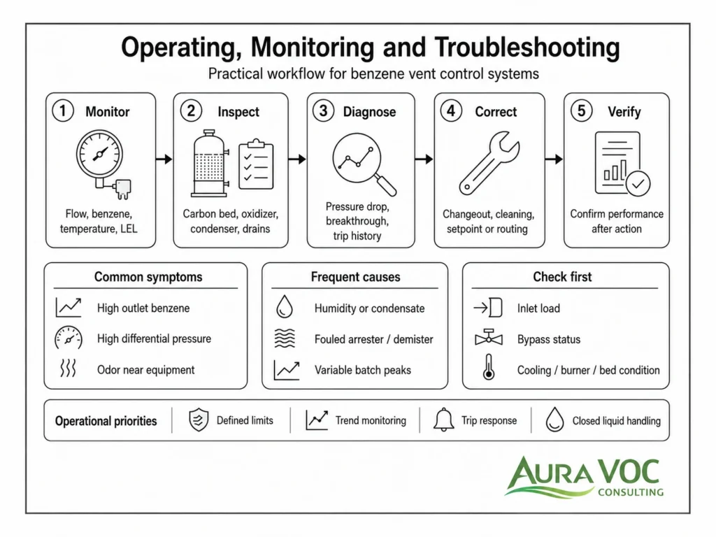
The control device is only one part of the system. Benzene vent control also depends on the process equipment, vent header, pressure control strategy, and operating procedures upstream of the abatement unit. If these constraints are not evaluated early, the plant may install a device that removes benzene under test conditions but creates process instability, excessive backpressure, or maintenance problems in daily operation.
Vacuum System Performance and Backpressure Sensitivity
Vacuum systems are often sensitive to added resistance. Routing a vacuum pump exhaust through a carbon bed, condenser, oxidizer inlet, flame arrester, or long header can increase discharge pressure and reduce vacuum performance. For liquid ring pumps, this can affect capacity and seal-liquid behavior. For dry pumps, elevated discharge pressure can affect motor load, temperature, and reliability. For ejector systems, downstream pressure can reduce achievable vacuum.
Backpressure can also change emissions behavior. If the vacuum system cannot maintain the intended pressure profile, the process may operate at higher temperature, longer batch time, or altered solvent removal rate. These changes can shift where and when benzene is released. Therefore, pressure drop should be reviewed not only for fan sizing but also for its effect on the process step generating the vent.
Reactor, Tank and Column Pressure Control
Reactors, tanks, and columns may rely on controlled venting to maintain pressure within a narrow operating range. Adding ductwork, isolation valves, flame arresters, demisters, or control equipment can change the pressure response of the system. In some cases, this can lead to sluggish pressure control, increased fugitive emissions from weak points, or unintended venting through relief or conservation devices.
Distillation columns are particularly sensitive to pressure. A change in overhead pressure can affect separation performance, condenser duty, vapor load, and temperature profile. Tanks operating under nitrogen blanketing may also be affected if vent header pressure interferes with breathing, filling, or emptying rates. For this reason, the vent control design should be checked against the process pressure-control requirements, not treated as a downstream utility connection.
Vent Header Routing and Condensate Management
Vent header design can determine whether the abatement system receives a stable vapor stream or a mixture of vapor, liquid slugs, aerosols, and variable pressure pulses. Benzene-containing vapors may condense in long duct runs, especially where ambient temperatures are low, lines are uninsulated, or the stream is close to saturation. If the header has poor slope, low points, or inadequate drains, condensate can accumulate and create intermittent liquid carryover.
Condensate management should be designed intentionally. Low-point drains, knockout vessels, heat tracing, insulation, demisters, and liquid seals may be required depending on the stream. Drained liquids should be collected in closed systems where benzene content is possible. Open buckets, floor drains, or temporary hoses can become secondary emission sources and create unnecessary exposure and housekeeping problems.
Flame arresters and detonation arresters require maintenance access and differential pressure monitoring. In dirty or condensable service, they can foul and become a major pressure drop contributor. This should be considered during layout, not discovered after commissioning.
Compatibility Between Multiple Vents Routed to One System
Centralizing several vents into one control system can reduce equipment count, but it can also introduce compatibility problems. Vents may differ in oxygen content, moisture, temperature, benzene concentration, solvent composition, corrosive components, and operating schedule. When these streams mix, the combined vent may be less predictable than any individual source.
Cross-contamination is a practical concern in multiproduct plants. A vent from one process can backflow or migrate into another line if isolation and pressure control are inadequate. Condensation of mixed solvents can also create liquid compositions that were not considered in the original waste handling plan. Where incompatible chemistries are present, segregation may be more reliable than a single common header.
Benzene Abatement Technology Selection
Technology selection should be based on measured or defensible process data, not on a default preference for one control method. The same benzene mass flow may point to different solutions depending on concentration, total flow, operating schedule, moisture, LEL risk, and whether the plant prefers destruction, recovery, or staged control. For EU chemical-sector installations, the European Commission WGC BREF provides BAT context for common waste gas management and treatment systems.
Activated Carbon Adsorption for Low-Flow or Intermittent Benzene Vents
Activated carbon is often considered for low-flow, intermittent, or moderate-concentration benzene vents. It can be straightforward to install and does not require combustion utilities, but its reliability depends on correct sizing, inlet conditioning, monitoring, and changeout practices.
The main operating issue is breakthrough. Benzene breakthrough can occur earlier than expected when the stream contains high humidity, competing VOCs, elevated temperature, or concentration peaks. As the adsorption zone moves through the bed, outlet benzene can rise quickly once the mass transfer zone reaches the outlet side. For benzene service, outlet monitoring and documented changeout criteria are more reliable than calendar-based replacement alone.
Carbon systems also require attention to heat generation and fire risk, especially with high organic loading or strongly adsorbed compounds. Bed temperature monitoring, inlet load control, pre-filtration, knockout protection, and safe spent carbon handling should be part of the design. Differential pressure should also be monitored because fouling, liquid carryover, bed settling, or particulate loading can affect flow distribution.
Thermal Oxidation for Variable or Mixed VOC Loads
Thermal oxidation can be appropriate for mixed VOC streams, variable solvent compositions, or cases where destruction is preferred over recovery. It is often more tolerant of complex organic mixtures than adsorption or condensation, provided the stream is properly conditioned and operated within safe flammability limits.
The main tradeoffs are fuel demand, temperature control, pressure drop, and trip management. Dilute benzene streams may require significant auxiliary fuel. High-load batch peaks may create temperature excursions if not buffered or controlled. Regenerative thermal oxidizers can reduce fuel use but add pressure drop and may not suit every vent system, especially where the upstream process is pressure-sensitive.
Operational reliability depends on maintaining combustion temperature, residence time, burner performance, airflow control, and safety interlocks. The plant should define what happens if the oxidizer trips during production and whether affected process steps must pause, route to temporary control, or shut down.
Catalytic Oxidation for Suitable Benzene-Containing VOC Streams
Catalytic oxidation can reduce operating temperature compared with thermal oxidation, which may lower fuel use for suitable streams. However, catalyst compatibility must be reviewed carefully. Compounds containing sulfur, phosphorus, silicon, halogens, metals, or certain aerosols can poison or foul the catalyst. Even if benzene itself is oxidizable, the full vent composition determines whether catalytic treatment is appropriate.
Catalytic systems need stable inlet conditions and adequate pre-treatment. Mist eliminators, filters, condensate removal, and temperature control may be required. Batch peaks should be evaluated for potential temperature rise across the catalyst bed. A system designed for average loading can experience catalyst overheating or accelerated deactivation if short VOC peaks are not considered.
Condensation and Solvent Recovery for High-Concentration Benzene Vapors
Condensation is most relevant where benzene or benzene-containing solvent vapor is concentrated enough for recovery or load reduction. It may be used as the primary treatment step or as upstream conditioning before carbon adsorption or oxidation.
The key variables are inlet concentration, non-condensable gas flow, cooling temperature, heat exchanger duty, fouling potential, and condensate handling. High nitrogen purge, air in-leakage, or vacuum system discharge flow can reduce benzene partial pressure and limit condensation efficiency even when refrigeration capacity appears adequate. Fouled exchangers can increase outlet benzene concentration and shift load to downstream polishing equipment.
Condensed liquid should be treated as a controlled benzene-containing stream until analysis confirms otherwise. Receivers, drains, transfer pumps, and storage tanks can become secondary vent sources if they are not closed or routed to appropriate control.
Scrubbing or Absorption for Benzene Vapors
Water scrubbing is usually a poor standalone choice for benzene vapor control because benzene does not transfer efficiently into water under typical vent treatment conditions. If absorption is considered, it should be evaluated as a mass-transfer system with a defined absorbent, liquid-to-gas ratio, regeneration or disposal route, and secondary vent control.
Organic absorption may be feasible in specific cases, but it shifts benzene into a liquid phase. That liquid may require closed storage, regeneration, off-site disposal, or downstream treatment. The vent from the absorbent tank, spent liquid receiver, or blowdown system may also require control. A scrubber that reduces stack concentration while creating an unmanaged benzene-containing liquid stream is not a complete control solution.
Hybrid Systems: Condensation Plus Carbon or Oxidation
Hybrid systems are often more practical than a single control device when the vent profile is variable. A condenser can remove part of a high-concentration solvent load before the residual vapor is polished by carbon. A knockout vessel or condenser can protect an oxidizer from liquid carryover. A condenser followed by oxidation may be appropriate where recovery reduces the organic load but residual vapors still require destruction.
The advantage is that each component has a narrower duty: liquid removal, load reduction, polishing, or final destruction. The tradeoff is added pressure drop, instrumentation, controls, drains, maintenance tasks, and operating procedures. Hybrid systems should be justified by the actual vent profile, not added as a generic extra measure.
Key Design Tradeoffs in Benzene Vent Treatment
Technology selection should compare operating consequences, not only removal capability. In many plants, the limiting factor is not whether a technology can control benzene under ideal conditions, but whether it can do so with the available pressure, utilities, maintenance practices, production schedule, and waste handling route.
Destruction vs Recovery
Destruction technologies such as oxidation reduce vapor-phase benzene by converting it rather than recovering it. This can simplify liquid waste handling but may increase fuel use, fan power, safety controls, and trip-related production constraints.
Recovery technologies such as condensation may reduce operating cost where solvent value or high vapor concentration supports recovery. However, they create benzene-containing liquid streams that require controlled handling. Adsorption can also be considered a transfer technology unless the carbon is regenerated and the recovered stream is properly managed. The comparison should include where the benzene mass goes after treatment.
Centralized vs Local Abatement
Centralized abatement can be efficient when vents are compatible and can be routed without excessive pressure drop. It can also simplify stack monitoring and reduce equipment count. However, it may create long headers, complex isolation requirements, cross-contamination risk, and shared downtime.
Local abatement can reduce duct routing and prevent incompatible streams from mixing, but it increases the number of assets requiring maintenance, monitoring, spare parts, and inspection. For multiproduct plants, a mixed approach is often more practical: local control for incompatible or high-risk vents, and centralized treatment for compatible lower-risk streams.
Carbon Adsorption vs Oxidation
Carbon adsorption may be lower in utility demand and easier to install for intermittent low-flow vents. Oxidation may be more robust for variable mixed VOC streams or higher total organic loads. The choice depends on whether the plant can manage carbon breakthrough, temperature monitoring, media handling, and spent carbon logistics, or whether it is better equipped to manage combustion systems, fuel demand, interlocks, trips, and stack testing.
A carbon system can be a poor fit if the vent contains high humidity, frequent solvent peaks, or condensable liquid carryover. An oxidizer can be a poor fit if the stream is very dilute, highly variable, pressure-sensitive, or difficult to keep within safe LEL limits. The decision should be based on the vent profile rather than a general preference.
Condensation Upstream of Final Control
Pre-condensation can reduce downstream load, recover solvent, and protect carbon or oxidation equipment from high vapor concentrations. It can also add refrigeration demand, fouling risk, condensate handling, and maintenance requirements.
The decision should be based on vapor-liquid behavior and operating variability. If high non-condensable flow limits condensation, downstream polishing may still receive substantial benzene load. If the condenser produces a mixed organic-water condensate, the plant must confirm how that liquid will be collected, stored, treated, and vented.
Dilution, Inerting and LEL Control
Dilution can reduce flammability risk but increases system flow, pressure drop, equipment size, and energy use. Inerting can improve safety at the source but may limit combustion options or require controlled oxygen addition. The preferred approach depends on the process, vent composition, safety basis, and selected abatement technology.
These decisions should be integrated early because they affect the entire system design. A dilution strategy selected for LEL control can change fan sizing and oxidizer fuel demand. An inerting strategy selected for process safety can change whether thermal or catalytic oxidation is feasible without additional conditioning.
Pressure Drop and Energy Implications
Pressure drop should be evaluated as a process constraint, not only a fan-sizing calculation. Benzene vent control equipment can change vacuum performance, tank breathing behavior, column pressure, reactor pressure control, and relief-device interaction.
A useful pressure-drop review should include the clean design condition and the expected fouled condition. Demisters, flame arresters, carbon beds, heat exchangers, dampers, RTO media beds, and long duct runs can all accumulate resistance over time. The plant should establish a baseline differential pressure after commissioning and trend it during operation.
Main Pressure Drop Contributors in VOC Vent Control Systems
The main pressure-drop contributors are usually ductwork, elbows, isolation valves, flame arresters, demisters, knockout vessels, carbon beds, heat exchangers, catalyst beds, RTO beds, stack dampers, silencers, and the stack itself.
In wet or condensable service, flame arresters and demisters deserve special attention. They can foul faster than expected and become the controlling restriction in the system. Carbon beds can also increase in resistance due to liquid carryover, fines, bed compaction, or particulate loading. Differential pressure taps should be located so operators can identify where the restriction is developing, rather than only seeing total system pressure loss.
Effects on Process Equipment and Venting Stability
Backpressure can reduce vacuum pump capacity, affect liquid ring pump seal-water behavior, increase dry pump discharge temperature, or reduce ejector performance. In tank systems, added resistance can interfere with nitrogen blanketing, filling, emptying, or conservation vent operation. In distillation service, overhead pressure changes can affect condenser duty, separation performance, and vapor load.
The abatement system should therefore be checked against the process pressure-control requirements. If the control device requires a fan, the fan curve, control strategy, turndown, and failure mode should be reviewed against the connected process equipment.
Fan and Blower Selection for Benzene-Containing Vent Streams
Fan selection should consider flow variability, corrosive or solvent-laden service, hazardous area classification, seal design, redundancy, turndown, and maintenance access. A fixed-speed fan may be acceptable for a stable continuous vent, while variable-speed control may be needed for batch or multi-source systems.
Materials of construction should be selected for the full stream composition, not for benzene alone. Many benzene-containing vents also include water vapor, chlorinated compounds, acids, particulates, or other solvents. Fan seals, bearings, drain points, and inspection ports should be reviewed for the expected service conditions.
Energy Demand by Abatement Technology
Energy comparison should include more than nameplate power. A refrigerated condenser may reduce downstream carbon consumption but add compressor maintenance and electrical load. A thermal oxidizer may reduce solvent disposal issues but require auxiliary fuel during dilute operation. An RTO can lower fuel use but add media-bed pressure drop, purge-cycle considerations, and fan power. Carbon adsorption may have low utility demand but can create recurring media, labor, and disposal costs.
The most useful comparison is an operating-cost and reliability comparison under the expected production schedule, including idle periods, batch peaks, seasonal cooling limitations, and control-device downtime.
Wastewater and Liquid Waste Implications of Benzene Vent Control
Benzene vent control can move benzene from vapor phase into liquid phase. That may be acceptable, but only if the liquid route is closed, controlled, and compatible with the site’s waste handling system. For facilities subject to U.S. air toxics requirements, EPA benzene waste operations rules can also affect tanks, drains, separators, closed-vent systems, and control devices.
Benzene-Containing Condensate from Vent Gas Cooling
Condensers, knockout vessels, chilled receivers, and low-point drains can generate benzene-containing liquid. This liquid may be recovered solvent, mixed condensate, contaminated water, or a two-phase mixture. It should be treated as benzene-containing until analysis shows otherwise.
The receiver itself can become a vent source. If condensate is collected in an open container, transferred through temporary hoses, drained to an open sump, or stored in an unvented tank, emissions may simply move from the process vent to the liquid handling area. Closed collection and appropriate receiver vent routing should be included in the design.
Scrubber Blowdown and Absorption Liquids
Where scrubbing or absorption is used, benzene is transferred into a liquid stream. This creates requirements for blowdown control, liquid storage, treatment or disposal. Water scrubbing is generally limited for benzene vapor removal, but even partial absorption can produce liquid streams that need review.
The liquid handling system should be included in the abatement design basis. Otherwise, the project may solve a stack issue while creating wastewater or waste management constraints. Absorbent tanks, recirculation vessels, blowdown containers, and treatment units may also have vent emissions that need to be routed or controlled.
Wastewater Tanks, Separators and Drains as Secondary Emission Sources
Benzene can re-enter the vapor phase from wastewater tanks, equalization basins, oil-water separators, floor drains, vacuum pump seal-liquid systems, scrubber blowdown, and condensate handling points. This is especially relevant where vent condensate, solvent washings, or seal liquid enters the wastewater system.
A practical review should follow the benzene mass beyond the primary control device. If the abatement system condenses or absorbs benzene, the downstream storage, transfer, treatment, and venting route must be reviewed. Otherwise, the plant may reduce one controlled emission point while creating several smaller uncontrolled sources.
Avoiding Air-to-Water Pollution Transfer During Abatement Design
Air-to-water transfer is a common design oversight. Condensation, scrubbing and absorption may reduce vapor-phase benzene, but they do not eliminate benzene mass from the plant. The engineering review should define where the benzene goes, how it is contained, and whether that route is compatible with the site’s wastewater and waste handling systems.
This review should include condensate receivers, vacuum pump seal-liquid discharge, scrubber blowdown, closed drains, wastewater tanks, separators, and treatment system vents. If these points are not included, the abatement system may appear effective at the stack while increasing emissions or handling risk elsewhere.
Monitoring, Maintenance and Operating Limits
Reliable benzene control depends on defined operating limits and routine verification. The abatement unit should not be treated as passive equipment. It should have operating parameters that correspond to the design basis and can be reviewed by operations, maintenance, and EHS personnel.
Critical Operating Parameters to Track
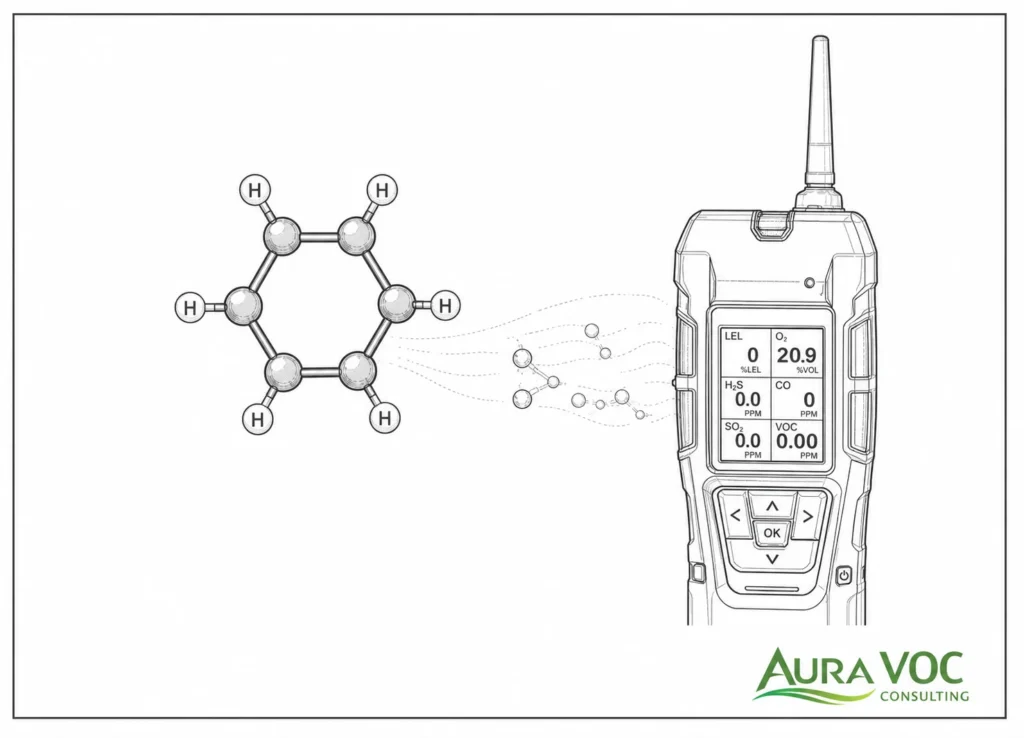
Key parameters include inlet and outlet VOC or benzene concentration, vent flow, temperature, oxygen, LEL, differential pressure, fan status, and bypass valve position. These values help confirm that the system is operating within the design envelope.
For batch processes, monitoring should capture peak conditions, not only stable operation. Alarm limits should be based on process risk and equipment capability. If a critical parameter drifts outside the operating range, the response should be defined before the event occurs.
Carbon Bed Monitoring and Changeout Criteria
Carbon beds require outlet monitoring, differential pressure checks, and temperature monitoring. Changeout should be based on breakthrough risk and measured performance, not only operating hours. High humidity, competing VOCs, elevated temperature, and batch peaks can shorten bed life.
A practical changeout plan should define sample location, sampling frequency, breakthrough threshold, maximum bed temperature, differential pressure limits, and response actions. If breakthrough occurs earlier than expected, the inlet conditions should be rechecked before simply replacing the carbon.
Oxidizer Monitoring and Maintenance
Oxidizers require verification of combustion temperature, residence time, burner condition, airflow, heat exchanger performance, and safety interlocks. Catalytic systems also require catalyst condition checks and protection from poisons or fouling.
Maintenance should include burner tuning, valve inspection, fan inspection, heat exchanger cleaning, catalyst or media pressure drop tracking, and review of trip history. For batch vents, temperature trends should be compared with production steps to confirm whether VOC peaks are driving excursions or instability.
Condenser and Knockout System Maintenance
Condensers require inspection for fouling, refrigeration performance, condensate drainage, and mist eliminator condition. A small loss in cooling or separation performance can increase downstream benzene load and shorten carbon bed life or increase oxidizer load.
Knockout vessels and demisters should be inspected for liquid level control, carryover, plugged drains, fouling, and corrosion. Condensate handling equipment should be checked for closed routing and vent control, not only liquid removal.
Bypass, Startup, Shutdown and Control Device Trip Management
The plant should define what happens during control device outage, bypass, startup, and shutdown. Bypass positions should be alarmed and logged where relevant. If production must stop during an abatement trip, this should be part of the operating procedure.
Startup and shutdown conditions should be included in the control philosophy. Some systems require warm-up, purge, isolation, or minimum flow before accepting process vents. These requirements should be aligned with the production sequence so operators are not forced into temporary workarounds.
Troubleshooting Benzene Emission Control Problems
Troubleshooting should start with the symptom, then move upstream through the process step, collection system, conditioning equipment, and final control device. Replacing media or adjusting setpoints without confirming the root cause often gives only temporary improvement.
Benzene Detected Downstream of a Carbon Bed
First checks should include inlet benzene concentration, total VOC load, humidity, bed temperature, operating hours since changeout, outlet sample location, and recent process changes. If benzene appears earlier than expected, review whether the bed has been exposed to higher peak loads, water vapor, competing solvents, liquid carryover, or poor flow distribution.
Channeling should also be considered. Uneven inlet flow, bed settling, poor distributor design, or bypass leakage can allow breakthrough before the calculated carbon capacity is reached. In this case, replacing carbon may not solve the underlying problem.
High Differential Pressure in the Vent System
High differential pressure should be localized before major equipment changes are made. Check flame arresters, demisters, knockout vessels, carbon beds, low-point drains, dampers, and duct sections. Condensate accumulation is a common cause where vent lines are long, uninsulated, poorly sloped, or exposed to seasonal temperature changes.
Compare current readings with the clean baseline. A gradual increase may suggest fouling or carbon bed loading. A sudden increase may indicate liquid accumulation, blocked drainage, valve position error, or a failed demister.
Oxidizer Temperature Instability or Frequent Trips
Review the inlet VOC profile against actual batch events. Temperature instability may be caused by high VOC peaks, low heating value during dilute operation, burner turndown limits, airflow imbalance, LEL interlocks, or unstable fan control. For RTOs, valve sequencing and purge behavior should also be checked. For catalytic units, catalyst differential pressure, inlet temperature, and catalyst bed temperature rise should be trended.
A frequent trip history often indicates that the oxidizer was selected for an average load but is being operated against variable process conditions. The solution may require better inlet load characterization, buffering, revised control logic, upstream condensation, or operating restrictions during specific batch steps.
Condenser Underperformance
Condenser performance should be checked against cooling medium temperature, exchanger fouling, inlet vapor temperature, non-condensable gas rate, condensate drainage, and outlet vapor concentration. High nitrogen purge, air in-leakage, or vacuum system discharge flow can reduce benzene partial pressure and limit condensation efficiency.
Seasonal cooling conditions should also be reviewed. A condenser that performs adequately in winter may send higher benzene load to the downstream carbon bed during summer cooling-water conditions. Trending outlet VOC or benzene concentration against cooling medium temperature can help identify this pattern.
Benzene Odor or Detection Near Equipment
Local benzene detection should trigger a mechanical and procedural review. Check sampling ports, open condensate receivers, vacuum pump discharge points, seal-liquid systems, drain seals, flange gaskets, relief valves, temporary hoses, and maintenance drain points.
Do not assume the source is the main stack. Small leaks around liquid handling, sampling, or vacuum equipment can be more relevant for worker exposure and plant housekeeping than the controlled stack discharge.
Practical Workflow for Evaluating Benzene Process Vent Controls
A structured workflow helps avoid technology selection before the vent system is understood. The evaluation should connect source behavior, collection design, control-device selection, wastewater handling, and operating limits.
Step 1 — Build a Benzene Vent Source Inventory
List each vent source, connected equipment, operating mode, expected benzene presence, routing, and current control method. Include intermittent vents, maintenance drains, vacuum exhausts, condenser vents, and wastewater-related vents. For multiproduct plants, note which campaigns or recipes may introduce benzene.
The inventory should also identify whether each vent is continuous, intermittent, batch-related, maintenance-related, or abnormal-operation related. This helps separate routine emission sources from vents that only appear during specific production or cleaning steps.
Step 2 — Measure Flow, Benzene Concentration and Peak Conditions
Sampling should match the operating profile. For batch processes, collect data during charging, heat-up, distillation, vacuum pull-down, purge, cleaning, and shutdown where relevant. For continuous processes, confirm whether the stream is actually stable across feed changes, temperature changes, and utility conditions.
Measured data should include both benzene concentration and total VOC load. Flow and concentration should be recorded together so mass loading can be calculated for normal and peak cases. If existing data is from a different campaign, season, or production rate, its relevance should be checked before use.
Step 3 — Screen Abatement Technologies Against Process Constraints
Compare carbon adsorption, oxidation, condensation, absorption, and hybrid systems against measured data. The screening should include flow range, benzene concentration, total VOC load, moisture, condensables, oxygen, LEL profile, pressure availability, utilities, maintenance capability, waste handling, and expected production schedule.
The screening should also consider operational resilience. A technology that looks attractive on capital cost may be a poor fit if it requires frequent media changeout, causes backpressure, creates difficult liquid waste, or cannot tolerate batch variability.
Step 4 — Check Pressure Drop, Wastewater and Safety Impacts
Before selecting equipment, confirm that the control approach does not create unacceptable backpressure, unstable pressure control, unmanaged condensate, wastewater emissions, unsafe flammability conditions, or difficult maintenance access.
This step should include fan curve review, relief and conservation vent interaction, LEL and oxygen control, condensate routing, wastewater venting, and access for inspection and cleaning. These issues are easier to address during design than after installation.
Step 5 — Define Monitoring, Maintenance and Operating Limits
Convert the design basis into field-operable limits. Define normal ranges, alarm points, shutdown conditions, sampling frequency, carbon changeout criteria, oxidizer operating limits, condenser maintenance tasks, bypass control, and trip response procedures.
The operating limits should be practical enough for plant use. If the control strategy depends on benzene outlet monitoring, differential pressure trending, LEL control, or condenser temperature, those values should be available to the personnel responsible for operating and maintaining the system.
When to Request an Engineering Review of Benzene Process Vents
An engineering review is useful when benzene vent behavior is uncertain, when existing controls are being modified, or when recurring operating problems suggest that the control system does not match the process conditions.
Before Installing a New VOC Abatement System
A review is useful before equipment selection, especially where benzene concentration, batch peaks, moisture, condensables, pressure drop, or LEL conditions are uncertain. At this stage, the main value is defining the correct design basis before capital is committed.
Before Routing Additional Vents to an Existing Control Device
Existing systems may not have capacity for added flow, VOC load, pressure drop, or incompatible chemistry. A new vent can also change oxygen content, moisture level, LEL profile, or solvent mix in the common header.
Before adding vents, the plant should confirm available capacity, fan operating margin, pressure effects on existing sources, control-device performance margin, and compatibility with current monitoring and maintenance procedures.
When Carbon Consumption or Breakthrough Increases
Increasing changeout frequency or outlet benzene detection usually indicates a change in inlet load, operating conditions, or bed performance. Possible causes include higher benzene concentration, new competing VOCs, elevated humidity, liquid carryover, bed channeling, or production changes.
An engineering review should compare current inlet conditions with the original design basis before assuming the carbon type or vessel size is the only issue.
When Oxidizer Trips, Backpressure or Wastewater Benzene Become Recurring Issues
Recurring operating problems often point to a mismatch between the process vent profile and the control system design. Oxidizer trips may indicate batch peaks, low heating value, LEL interlock issues, or airflow instability. Backpressure may indicate fouling, undersized ductwork, or fan control problems. Wastewater benzene may indicate that a condenser, scrubber, or drain system is shifting benzene to liquid phase without adequate downstream control.
These issues should be reviewed as system problems rather than isolated equipment failures.
Before Process Changes, Solvent Substitution or Production Expansion
Management-of-change reviews should include benzene vent effects, not only process yield, safety, and production capacity. A new raw material, solvent substitution, higher batch frequency, increased vacuum duty, or revised distillation step can change benzene emissions and control-device loading.
The review should confirm whether the existing abatement system can handle the new conditions and whether sampling, monitoring, operating limits, or wastewater handling procedures need to be updated.
FAQ
What data is needed to size a benzene VOC abatement system?
The minimum design basis should include vent flow range, benzene concentration, total VOC concentration, temperature, moisture, oxygen content, LEL profile, condensables, operating schedule, available pressure, utility constraints, and liquid waste route.
How should benzene emissions from batch process vents be sampled?
Sampling should be aligned with the batch steps that generate emissions, not only with convenient steady periods. Relevant events may include charging, heat-up, distillation, vacuum pull-down, nitrogen purging, cleaning, and shutdown.
Why can benzene break through an activated carbon bed earlier than expected?
Early breakthrough can result from higher-than-expected inlet concentration, high humidity, competing VOCs, elevated bed temperature, channeling, liquid carryover, poor flow distribution, or changeout intervals based only on operating hours.
How does moisture affect activated carbon performance for benzene vapors?
Moisture can compete for adsorption capacity, promote condensation, increase pressure drop, and reduce effective bed performance. Wet streams often require upstream cooling, knockout, demisting, or temperature control before carbon adsorption.
When should a condenser be installed upstream of a carbon bed or oxidizer?
A condenser should be considered when the vent contains high concentrations of condensable solvent vapor, when load reduction can extend carbon life, or when reducing oxidizer inlet load improves operating cost or stability. Condensate handling must be included in the design.
Can benzene emissions from vacuum pump exhaust be routed to a common VOC header?
Yes, but only after reviewing discharge pressure, flow variability, air in-leakage, seal-liquid handling, oxygen content, LEL risk, and compatibility with other vent sources. Added backpressure can affect vacuum performance.
What causes high pressure drop in a benzene vent control system?
Common causes include fouled flame arresters, fouled demisters, liquid accumulation in low points, saturated or compacted carbon beds, blocked duct sections, exchanger fouling, damper problems, and undersized ductwork.
How do you troubleshoot benzene detected after a VOC control device?
Start by confirming the sample location and analytical result. Then review inlet concentration, total VOC load, flow, moisture, temperature, bypass status, operating mode, control-device condition, and recent process changes.
Can benzene condensate create secondary emissions from wastewater tanks?
Yes. Condensed benzene can volatilize from receivers, drains, tanks, separators, seal-liquid systems, or wastewater treatment units if those systems are not closed or vented to control.
Should multiple benzene-containing vents be routed to one abatement system?
They can be routed to one system if the vents are compatible in flow, pressure, oxygen content, LEL profile, moisture, temperature, and chemistry. Incompatible or highly variable vents may require segregation, local control, or staged treatment.
What should be checked before adding a new process vent to an existing VOC control system?
Check available flow capacity, control-device loading, fan margin, header pressure drop, LEL and oxygen limits, solvent compatibility, condensate formation, monitoring coverage, and whether the existing operating permit or internal operating limits are affected.
Conclusion
Benzene emissions from process vents require an evaluation that connects the vent source, control device, collection system, and downstream liquid handling route. A design based only on average total VOC load can miss the conditions that usually determine performance: batch peaks, non-condensable flow, moisture, LEL limits, pressure drop, carbon breakthrough, condenser fouling, oxidizer trips, and benzene-containing condensate.
A practical control strategy should define which vents are routed to treatment, what peak conditions the system must handle, how pressure drop affects the process, where condensed or absorbed benzene goes, and what operating limits plant personnel must monitor. This is the difference between a control device that works during a test and a vent control system that remains reliable during production.
CTA
For facilities evaluating benzene-containing process vents, AuraVOC can review measured flow and concentration data, vent routing, abatement technology options, pressure drop constraints, control-device operating issues, and wastewater transfer risks before equipment selection or modification.
A useful starting point is to compile the vent list, benzene concentration range, total VOC load, operating schedule, current control equipment, known breakthrough or trip history, available utilities, and liquid waste handling route.