
Cryogenic Condensation for VOC Abatement in Industrial VOC Emission Systems
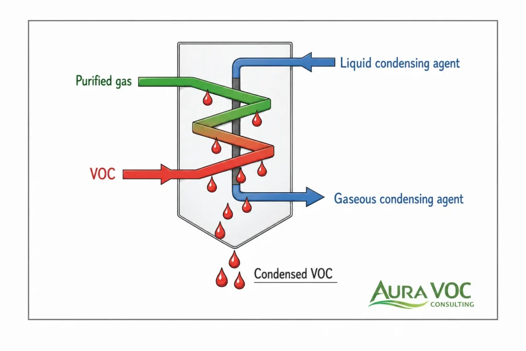
Cryogenic condensation is a VOC abatement and solvent recovery option used where an industrial exhaust stream contains condensable organic vapors at concentrations that justify low-temperature treatment. It is most relevant for defined process vents with meaningful solvent loading, intermittent peaks, or recoverable solvent value. It is usually less effective as a general treatment method for large, dilute ventilation streams.
The principle is simple: the VOC-laden gas is cooled until part of the organic vapor condenses into a liquid phase that can be separated from the carrier gas. The engineering assessment is more complex. Actual performance depends on VOC partial pressure, solvent mixture behavior, inlet temperature, water vapor content, heat exchanger design, pressure drop, residence time, condensate separation, instrumentation, and the required outlet concentration.
For plant managers, EHS managers, and process engineers, cryogenic condensation should not be evaluated only as an emissions-control package. It affects utility demand, production flexibility, process safety, hazardous condensate handling, maintenance workload, and downstream abatement requirements. A system that meets a theoretical removal target may still perform poorly if the real process has batch peaks, changing solvent recipes, high humidity, aerosol carryover, limited fan margin, or poorly defined defrost procedures.
This article focuses on how cryogenic condensation fits into industrial VOC abatement, where it is technically practical, and which operational constraints should be checked before treating it as a suitable option.
How Cryogenic Condensation Fits into Industrial VOC Abatement
Recovery-based VOC control rather than VOC destruction
Cryogenic condensation removes VOC mass by transferring solvent vapor from the gas phase into a liquid condensate. It does not destroy VOCs. That distinction affects the complete design basis because the plant must manage both the treated gas stream and the recovered liquid stream.
The recovered condensate may be suitable for reuse, sent to a solvent recovery unit, or handled as hazardous waste. The route depends on solvent purity, water content, campaign cross-contamination, reaction by-products, and site quality requirements. In batch plants, condensate from different products or solvent campaigns should not be assumed reusable without confirming compatibility and segregation requirements.
Recovery efficiency also should not be treated as equivalent to stack compliance. A condenser can recover a large fraction of solvent mass while still leaving residual VOC concentration above the required outlet limit, especially where the stream contains lighter solvents or mixed VOCs with different vapor pressures.
Typical industrial emission sources suited to cryogenic condensation
Cryogenic condensation is normally evaluated for defined process vents rather than broad plant ventilation. Typical candidate sources include reactor vents, vessel vents, solvent charging systems, tank loading vents, dryer exhausts, centrifuge vents, vacuum pump exhausts, and contained solvent handling operations.
The common feature is not the industry sector itself, but the emission profile: moderate flowrate, meaningful solvent loading, predictable operating steps, and limited dilution air. A segregated reactor vent may be a stronger candidate than a combined exhaust header that also includes general room extraction. Source segregation can be as important as the condenser design because dilution increases cooling load without increasing recovered solvent mass.
When cryogenic condensation is used alone versus before polishing
Cryogenic condensation can operate as a standalone system when the target compounds condense at achievable temperatures and the required outlet concentration is not too low. This is more likely for concentrated streams containing recoverable solvents with favorable condensation behavior.
Where outlet limits are stringent, or where part of the solvent mixture remains volatile at the selected operating temperature, a polishing stage may be required. Activated carbon is often considered after condensation when residual VOC loading is low enough to avoid rapid saturation. Oxidation may be used where destruction is required or where recovered condensate has limited value.
The correct configuration depends on outlet concentration requirements, solvent composition, nitrogen cost, fan margin, and downstream operating constraints.
Difference from activated carbon, thermal oxidation, and scrubbing
Cryogenic condensation should be compared against other VOC abatement technologies using site-specific operating data, not only removal efficiency. Activated carbon may be practical for lower residual concentrations but can become difficult at high solvent loading due to saturation rate, temperature rise, and changeout frequency. Thermal oxidation destroys VOCs but does not recover solvent and may introduce fuel, corrosion, or acid gas considerations depending on the compounds present. Scrubbing is only effective where the target compounds are soluble or chemically reactive in the selected liquid phase.
Condensation is strongest where the plant benefits from recovering or removing bulk solvent mass before the final treatment step.
When Cryogenic Condensation Is a Practical Fit for VOC Emissions
High-concentration solvent vapor streams
Cryogenic condensation is most practical when the gas stream contains a significant VOC mass load. The higher the VOC partial pressure, the more favorable the condensation behavior and the more meaningful the recovered solvent quantity.
A dilute stream may still contain VOCs above a permit threshold, but that does not automatically make condensation a good fit. If the carrier gas volume is large and the VOC concentration is low, the system must cool a large quantity of gas to recover a relatively small amount of solvent. In that case, liquid nitrogen demand, exchanger size, and fan impact can become disproportionate to the removal benefit.
Low to moderate gas flowrates
Low to moderate flowrates are generally more favorable for cryogenic condensation because they reduce heat exchanger size, cooling duty, pressure drop, and control difficulty. They also make it easier to maintain stable outlet temperature during variable operation.
High-flow exhausts are not impossible, but they require careful review. Large volumes of carrier gas increase sensible cooling load even when VOC mass is modest. If the source can be segregated from general ventilation or captured closer to the process equipment, condensation may become more practical.
Batch, intermittent, and peak VOC emissions
Batch processes can be good candidates for cryogenic condensation, but only when the system is designed around real emission profiles rather than daily averages. Short-duration VOC peaks can drive condenser capacity, nitrogen valve sizing, separator volume, and downstream polishing load.
Intermittent operation also creates practical questions. The system may need defined start-up, cool-down, standby, and shutdown procedures. If the condenser is kept cold between batches, nitrogen use may continue during non-production periods. If it is warmed and cooled repeatedly, thermal cycling, start-up time, and operator discipline become more important.
Solvents with recovery value
Cryogenic condensation is more attractive when the condensed solvent has recovery value or when reducing solvent loss has a clear process benefit. This is common in pharmaceutical, specialty chemical, coatings, and solvent handling applications where emissions may contain high-value or high-volume organic compounds.
Recoverability must be assessed realistically. Mixed-solvent condensate, water contamination, impurities, degradation products, or incompatible compounds may prevent direct reuse. In some cases, the recovered liquid is still useful as feed to a solvent recovery unit. In other cases, it becomes hazardous waste.
VOC streams where oxidation or carbon adsorption may be constrained
Cryogenic condensation is often evaluated when carbon bed loading, oxidizer fuel demand, solvent recovery value, or compound chemistry makes other abatement routes less attractive.
Activated carbon may be problematic for high VOC loading, difficult-to-regenerate solvents, high humidity, or streams with thermal risk during adsorption. Oxidation may be less attractive where solvent recovery is preferred, fuel demand is high, VOC concentration is highly variable, or the stream contains compounds that create corrosion or acid gas concerns after combustion.
Condensation can also reduce the load before these technologies. Removing bulk solvent upstream of carbon can extend bed life. Reducing VOC concentration before an oxidizer can stabilize operation depending on the case.
Poor-fit cases: dilute, humid, high-flow, or low-boiling VOC streams
Cryogenic condensation is not a universal VOC abatement solution. It may be a poor fit for very dilute emissions, very high gas flowrates, highly humid streams without water management, or compounds that require extremely low temperatures to condense.
Humidity is a frequent practical limitation. Water vapor can freeze, increasing pressure drop, blocking exchanger passages, affecting drains, and forcing defrost cycles. Some organic compounds or impurities may also freeze or crystallize at low temperature.
Low-boiling or highly volatile compounds may require deep cooling to achieve the desired outlet concentration. At some point, additional cooling may be less practical than using condensation for bulk recovery followed by another abatement step.
Industrial Applications and Emission Sources
Pharmaceutical batch process vents
Pharmaceutical plants often generate VOC emissions from batch operations rather than steady continuous exhausts. Reactor charging, solvent transfer, drying, filtration, centrifugation, vacuum breaking, and vessel cleaning can all produce short-duration solvent peaks.
Cryogenic condensation can be relevant where the vent stream contains recoverable solvents and the gas flowrate is not dominated by dilution air. The main design challenge is variability. A condenser sized only for average emissions may underperform during solvent displacement, heated drying, or depressurization. Campaign changes also matter because each solvent recipe can change condensation behavior, freezing risk, and recovered liquid quality.
Chemical reactor and vessel vents
Chemical reactors, receivers, blend tanks, and intermediate vessels may release VOCs during filling, heating, agitation, nitrogen blanketing, depressurization, or transfer operations. These sources can have higher VOC partial pressures than general ventilation streams, making them better candidates for condensation.
The first check is whether the vent composition is stable enough to define a reliable design case. Reaction by-products, acid gases, aerosols, or entrained liquid droplets can affect fouling, corrosion, condensate classification, and downstream polishing requirements. For reactor vents, the evaluation should include normal operating emissions and credible transition conditions, especially where interlocks route the process to bypass or emergency vent systems.
Solvent storage tank and loading vents
Storage tanks and loading operations produce VOC emissions through vapor displacement, breathing losses, and transfer-related venting. Cryogenic condensation may be considered where vapor concentration is high enough and the vent flow can be captured without excessive dilution.
For loading applications, the emission profile is often tied to transfer rate. This can make the system easier to characterize than a highly variable process vent, but the design must still account for peak displacement flow, vapor composition, tank temperature, and nitrogen blanketing. Condensate return or recovery should be reviewed carefully because recovered liquid may contain mixed vapors from different tanks or traces of water from the vent header.
Dryer, centrifuge, and vacuum pump exhausts
Dryers, centrifuges, and vacuum systems can produce concentrated solvent emissions during specific phases of operation. These sources are common in pharmaceutical, fine chemical, and specialty manufacturing plants.
Vacuum pump exhausts require particular attention because they may contain solvent vapor, seal fluid mist, water vapor, and non-condensable gases. Dryers may produce changing vapor composition as the batch progresses, with high solvent load at the beginning and lower concentrations later. Centrifuge vents may contain aerosols or fine droplets that require upstream knock-out or mist elimination before the cryogenic exchanger.
Without adequate pre-separation, fouling and carryover can reduce performance and increase maintenance frequency.
Coatings, paint, and solvent handling operations
Coatings and paint operations can involve solvent-rich emissions from mixing, filling, cleaning, and transfer steps. Cryogenic condensation is usually more relevant for contained or semi-contained solvent handling vents than for large booth ventilation streams, which are often high-flow and comparatively dilute.
Where coating lines produce intermittent solvent peaks, condensation may be evaluated as a load-reduction stage. The system design must account for cleaning solvents, formulation changes, and possible aerosol carryover. If the exhaust contains paint solids, resins, or sticky materials, upstream filtration or source segregation may be required to protect the heat exchanger.
Specialty manufacturing processes with recoverable solvents
Specialty manufacturing plants often use solvents in smaller but higher-value process streams. Cryogenic condensation may be suitable where the plant has defined vent sources, moderate flowrates, and a practical route for recovered condensate.
These applications require careful solvent compatibility review. Some streams may include monomers, inhibitors, reactive vapors, or compounds that crystallize at low temperature. The design basis should confirm not only condensation performance but also whether the condensed material remains pumpable, drainable, and safe to store at expected operating temperatures.
Design Inputs That Determine Cryogenic Condenser Performance
VOC composition and solvent partial pressure
A cryogenic condenser should be designed around compound-specific vapor behavior, not a generic total VOC number. Each solvent has its own vapor pressure, freezing point, latent heat, and condensation profile. A mixed stream containing acetone, ethanol, toluene, hexane, or chlorinated solvents will not behave as a single compound.
This matters in real plant operation. A system may recover heavier or less volatile solvents efficiently while lighter compounds remain in the outlet gas. If the permit or internal target is based on a specific compound, total solvent recovery may not be the controlling criterion. Campaign changes can also shift the outlet profile; a condenser setpoint that works for a toluene-rich emission may not be adequate for a more volatile solvent blend.
Peak and average VOC mass loading
Average VOC loading is useful for estimating solvent loss and annual operating cost. It is not sufficient for equipment sizing. Cryogenic systems must be checked against peak mass loading during charging, depressurization, drying, vacuum breaking, tank loading, or other short-duration events.
The design basis should define minimum, normal, and peak VOC load, with the duration and frequency of each operating mode. Peak load affects heat exchanger duty, nitrogen valve capacity, condensate separator sizing, outlet VOC excursions, and downstream polishing load. Where batch data is unavailable, emission testing or temporary monitoring is often needed before specification.
Required outlet VOC concentration
The required outlet concentration sets the final operating temperature and determines whether condensation alone is realistic. Deeper cooling can reduce residual VOC concentration, but utility demand often increases sharply at lower temperatures.
The outlet requirement should be defined clearly as total VOC, compound-specific concentration, mass flow, or permit emission rate. These are not interchangeable. For mixed-solvent streams, the most volatile compound may drive the final design even if it represents a smaller share of the total solvent mass. Where regulatory terminology is relevant, confirm the applicable VOC definition before finalizing the outlet design basis.
Inlet gas temperature and humidity
Inlet temperature drives sensible cooling load. A warm process vent can consume substantial refrigeration capacity before any meaningful solvent condensation occurs. Where possible, heat recovery, upstream cooling, or source temperature control should be evaluated before accepting high liquid nitrogen consumption as unavoidable.
Humidity creates a separate reliability issue. Water vapor can freeze on cold surfaces, restrict exchanger passages, block drains, and force defrost cycles. For humid vents, the design should address water removal, staged cooling, heat tracing, drain protection, and defrost procedures before the system is placed into service.
Gas flowrate, turndown, and batch variability
Flowrate influences heat exchanger size, residence time, pressure drop, and control response. Low to moderate flowrates are generally more favorable. Large dilution air volumes increase refrigeration load and can make condensation uneconomic even when the VOC concentration appears relevant.
Batch turndown also matters. At low flow, the system may overcool, waste nitrogen, or experience unstable control. At peak flow, residence time can fall and outlet temperature can rise. The operating envelope should be based on measured or defensible process conditions, not a single nominal flowrate.
Pressure drop allowance and available fan margin
A cryogenic condenser adds resistance to the vent system. Clean pressure drop is only the starting point. Frost, mist, fouling, demister loading, and condensate accumulation can raise the operating pressure drop over time.
The available fan margin should be checked before equipment selection. Excess pressure drop can reduce capture efficiency, affect vacuum pump discharge conditions, change vessel venting behavior, or trigger bypass logic. Differential pressure alarm and trip values should be set from the process limits, not only from package equipment defaults.
Materials of construction and low-temperature compatibility
Materials must be suitable for the solvent mixture, condensate composition, and operating temperature. Low-temperature service can affect seals, gaskets, elastomers, instruments, and drain components. Thermal cycling during start-up, shutdown, or defrost can add mechanical stress.
If the stream contains water, chlorinated solvents, acid-forming compounds, or reactive by-products, corrosion review is required. Material selection should consider both normal operation and defrost conditions, where concentrated liquid mixtures may contact surfaces at changing temperatures.
Cryogenic Condensation System Configuration
Pre-cooling and heat recovery section
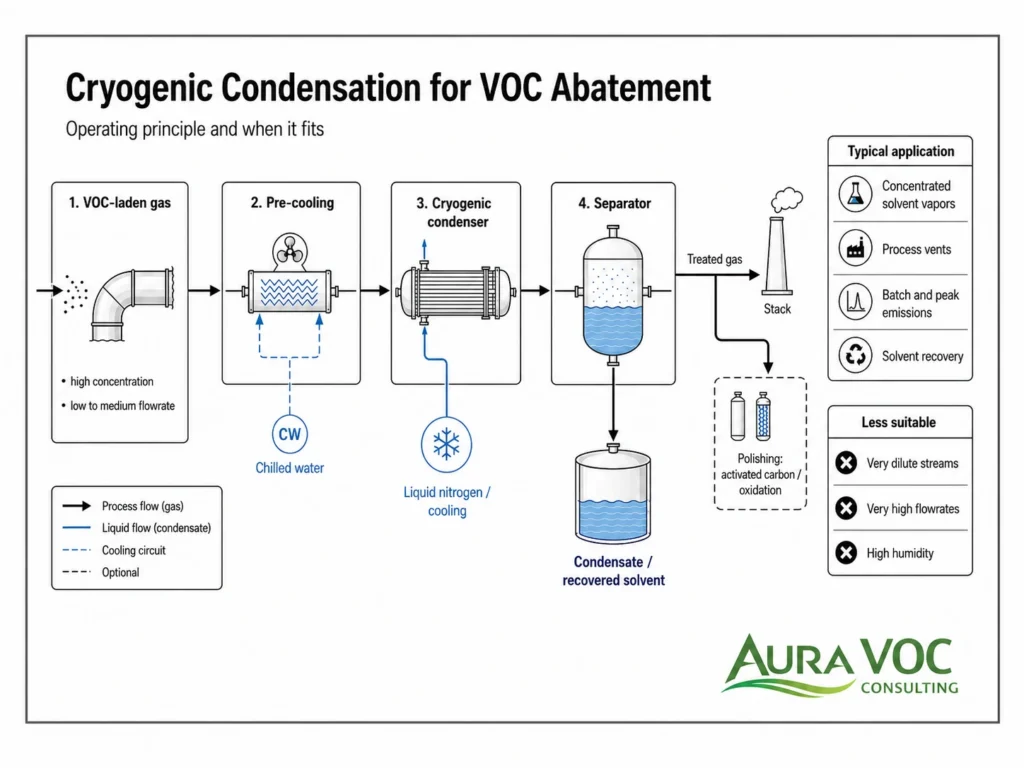
A pre-cooling section can reduce cryogenic utility demand by using cold treated gas to cool the incoming VOC-laden stream. This is often one of the most important efficiency measures in continuous or frequent-duty systems.
Heat recovery must be designed with fouling and condensation in mind. If VOCs, water, or aerosols condense in the wrong section, the exchanger may become difficult to drain or clean. The layout should maintain proper slopes, drainage points, access for inspection, and pressure drop monitoring.
Cryogenic condenser or low-temperature heat exchanger
The main cryogenic condenser provides the low-temperature duty required to condense target VOCs. Its design must balance heat transfer, residence time, pressure drop, cleanability, and frost tolerance.
A compact exchanger may reduce footprint and improve thermal performance, but narrow passages can be more sensitive to ice, solids, and viscous condensate. A more robust design may tolerate fouling better but require more space or higher capital cost. The preferred configuration depends on stream cleanliness, humidity, operating schedule, and maintenance expectations.
Direct liquid nitrogen injection versus indirect cooling
Direct liquid nitrogen injection cools the gas stream by mixing nitrogen directly into the exhaust. This can provide rapid cooling, but it increases outlet gas volume and dilutes the treated stream. It may also affect oxygen concentration, downstream equipment sizing, and gas monitoring interpretation.
Indirect cooling uses a heat exchanger so that nitrogen or another cryogenic medium does not directly contact the process gas. This can improve separation between utility and process streams and may support better condensate quality, but heat exchanger design becomes more critical.
The choice affects control response, nitrogen consumption, solvent recovery, outlet flowrate, analyzer interpretation, and downstream treatment requirements.
Single-stage versus multi-stage condensation
A single-stage system may be sufficient for simpler streams with limited water content and a defined solvent composition. Multi-stage condensation is often more practical where the stream contains water, heavy solvents, and lighter VOCs together.
Staging allows higher-boiling components or water to be managed before the coldest section. This can reduce freezing risk and improve condensate handling. It can also support separate collection of different condensate fractions, although this adds equipment, controls, and maintenance points.
Demister, separator, and condensate collection system
Condensed solvent must be separated from the gas stream before the outlet is routed to stack or polishing. Poor separation can create mist carryover, apparent VOC breakthrough, carbon bed contamination, or downstream fouling.
The separator and demister should be sized for expected condensate rate, gas velocity, turndown, and liquid properties. Drain design is equally important. Frozen, undersized, or poorly sloped drains can cause condensate accumulation, pressure drop increase, and unstable operation.
Outlet polishing with carbon adsorption, oxidation, or scrubbing
If condensation alone cannot meet the required outlet concentration, a polishing stage may be added. Activated carbon is commonly considered where residual VOC concentration is low enough to avoid rapid saturation. Oxidation may be appropriate where destruction is required and the remaining stream is compatible with the oxidizer design. Scrubbing may be relevant only for specific soluble or reactive compounds.
The polishing step should be sized based on actual expected outlet composition from the condenser, not only untreated inlet VOC concentration. Condenser performance, outlet temperature, humidity, and possible mist carryover can all affect downstream treatment reliability.
Instrumentation, alarms, and safety interlocks
A cryogenic VOC system should include instrumentation that supports both performance control and safe operation. Typical measurements include inlet and outlet temperature, differential pressure, nitrogen flow, condensate level, oxygen concentration where inerting is relevant, and outlet VOC concentration where required.
Alarm logic should address high pressure drop, low nitrogen supply pressure, high outlet temperature, high condensate level, abnormal oxygen level, analyzer fault, and unsafe bypass conditions. For flammable solvent streams, LEL monitoring and interlocks must be integrated with the plant’s process safety philosophy rather than treated as standalone package controls.
Liquid Nitrogen, Refrigeration Load, and Operating Cost Drivers
Sensible cooling load from the carrier gas
Sensible cooling of the carrier gas can dominate operating cost when flowrate is high and VOC concentration is modest. This is why dilution air is usually a design penalty for cryogenic condensation. Cooling excess air consumes nitrogen but does not increase solvent recovery.
Before sizing the condenser, the plant should check whether the VOC source can be captured closer to the process, separated from general ventilation, or operated with reduced purge flow. In many cases, reducing unnecessary carrier gas flow has a larger impact on nitrogen consumption than fine-tuning the final temperature setpoint.
Latent heat load from VOC condensation
The condenser must remove the latent heat released as VOC vapor condenses. This load follows the actual solvent mass entering the system, which may vary sharply during batch operation.
Peak solvent release can exceed average loading by a wide margin. If the nitrogen control valve, exchanger surface, or separator volume is sized around average duty, the system may perform normally most of the time but break through during the operating steps that drive compliance risk.
Effect of water vapor and ice formation on cooling demand
Water vapor adds both sensible and latent load. Under freezing conditions, it can form ice on exchanger surfaces. Ice does not only consume cooling capacity; it changes the hydraulic behavior of the exchanger.
A gradual rise in differential pressure, unstable outlet temperature, reduced condensate drainage, or more frequent defrosting often indicates that water load was underestimated. For humid streams, the cooling duty calculation should include water vapor and the operating plan should define how ice will be managed.
Impact of inlet temperature on nitrogen consumption
Inlet temperature should be treated as an operating cost driver. A warm process vent increases nitrogen demand before the condenser reaches the temperature range needed for solvent recovery.
Plants should review whether upstream process changes, heat recovery, or conventional pre-cooling can reduce the cryogenic duty. For high-duty systems, a cold outlet gas heat exchanger can recover useful cooling capacity, but it must be designed for drainage and fouling control.
Heat recovery using cold outlet gas
Using cold treated gas to pre-cool the incoming stream can reduce nitrogen consumption. The benefit is greatest where the system operates for long periods or handles consistent flow.
The heat recovery exchanger should not become an unplanned condensation zone that is difficult to drain or clean. If partial condensation occurs upstream of the main separator, the layout needs low-point drains, cleanout access, differential pressure monitoring, and materials suitable for the recovered liquid.
Fan energy and pressure drop implications
Fan power is usually smaller than nitrogen cost, but pressure drop can control operability. A condenser installed in an existing vent system can reduce capture velocity, increase vessel vent backpressure, or affect vacuum pump exhaust conditions if fan margin is limited.
The design should consider clean pressure drop, expected fouled pressure drop, demister pressure drop, and pressure drop at maximum flow. A system that meets thermal duty but constrains the upstream process is not a successful design.
Nitrogen storage, supply reliability, and site logistics
Liquid nitrogen supply is a site constraint, not just a utility line item. Storage volume, delivery frequency, vaporizer capacity, pressure regulation, low-level alarms, and vehicle access all affect reliability.
The plant should define what happens during low nitrogen pressure, delayed deliveries, or production campaigns with higher solvent load than normal. Options include production hold, bypass to an alternate abatement system, reduced operating rate, or controlled shutdown. These responses should be documented before operation, not improvised during a supply interruption.
Pressure Drop, Ice Formation, and Fouling Risks
How frost and ice increase pressure drop
Frost narrows exchanger passages, changes flow distribution, and reduces effective heat transfer area. The first indication is often a differential pressure trend rather than an immediate outlet VOC problem.
Operators should monitor clean baseline pressure drop, normal operating pressure drop, and the rate of increase during each campaign. A rapid increase may point to high humidity, drain flooding, or aerosol loading. A gradual increase over multiple batches may indicate fouling or incomplete defrost.
Solvent freezing and crystallization risks
Water is the most common freezing concern, but organic compounds, impurities, or reaction by-products can also solidify at low temperature. This is especially important for mixed-solvent streams, specialty chemical vents, and processes with solids or heavy organic residues.
Solvent freezing may show up as reduced drainage, solids in the condensate system, pressure drop increase, or loss of heat transfer after a campaign change. Minimum operating temperature should be checked against freezing behavior, not only condensation performance.
Aerosols, mist, and particulate fouling
Aerosols and entrained liquids can foul cold surfaces and overload demisters. Dryer exhausts, centrifuge vents, vacuum pump exhausts, and coating operations often need upstream separation or filtration before the cryogenic section.
When mist enters the condenser, it can freeze, form sticky deposits, contaminate recovered solvent, or carry through to downstream carbon. Source characterization should include aerosols and particulates, not only vapor-phase VOC concentration.
Drain blockage and condensate accumulation
Condensate must leave the cold section reliably. Blocked drains can flood exchanger passages, increase pressure drop, reduce gas-liquid separation, and create mist carryover.
Drain lines should have suitable slope, freeze protection, isolation access, and clear maintenance procedures. Low points in cold piping should be intentional and drainable; accidental low points often become collection points for solvent, ice, or solids.
Monitoring pressure drop as an early warning indicator
Differential pressure should be trended by operating mode. A single alarm setpoint is less useful than understanding how pressure drop behaves during start-up, peak solvent release, low-load operation, and defrost.
A pressure drop trend can help distinguish between ice formation, fouling, demister loading, and flooding. It also provides a maintenance trigger before outlet VOC concentration increases or the system is forced into bypass.
Design options to reduce fouling and blockage risk
Staged cooling, wider exchanger passages, upstream knock-out pots, demisters, heat-traced drains, and planned defrost logic can improve reliability. These features add cost and sometimes pressure drop, but they may be justified where humidity, aerosols, or solids are part of the real stream.
The preferred design should be selected from the stream characteristics, not from a standard package arrangement.
Condensate Handling and Wastewater Implications
Recovered solvent quality and reuse potential
Recovered solvent quality should be verified before assuming reuse. Condensate may contain water, multiple solvents, stabilizers, reaction by-products, dissolved gases, or fine solids. In pharmaceutical or specialty production, even small cross-contamination can prevent direct return to process.
A practical design should define sampling points, segregation strategy, storage requirements, and acceptance criteria for reuse or recovery. Without this, the system may recover solvent mass but create a liquid waste stream with limited value.
Water-solvent phase separation
Water and solvent may form separate phases, emulsions, or partially miscible mixtures. The separation behavior affects tank design, decanting procedures, level instrumentation, waste routing, and recovered solvent quality.
Where water content is significant, the system should include a defined method for handling the aqueous phase. Sending mixed condensate to a general wastewater system without review can create VOC stripping, hazardous classification, or treatment compatibility issues.
Defrost liquid and wastewater generation
Cryogenic condensation does not inherently generate high wastewater volumes, but defrost cycles can produce solvent-contaminated liquid. The defrost route should be defined in the design: where the liquid drains, whether it is segregated, how it is sampled, and whether it is treated as recovered solvent or waste.
Defrost operation can also create temporary emissions if the cold section is warmed while solvent remains in the equipment. Isolation, purge, and routing procedures should be reviewed for each installation.
Hazardous condensate storage and transfer
Condensate storage is part of the abatement system. Tanks, pumps, seals, vents, transfer lines, level instruments, and containment should be compatible with solvent properties and site hazardous area requirements.
The condensate tank vent may itself become a VOC source. It should be routed to an appropriate control point or designed with suitable vent treatment where required.
ATEX, grounding, containment, and compatibility considerations
Flammable recovered solvents require appropriate grounding, bonding, ignition source control, and area classification review. Materials of construction should be compatible with the solvent mixture and with low-temperature service where cold condensate can reach downstream components.
Secondary containment should account for the maximum credible liquid inventory, not only the normal condensate rate. Maintenance activities such as draining, sampling, and filter cleaning should also be included in the safety review.
When recovered condensate becomes waste instead of product
Condensate becomes a waste management issue when solvent purity is poor, phases are difficult to separate, incompatible campaigns share the same collection system, or contaminants prevent reuse. In those cases, disposal cost and storage requirements are part of the true operating cost of the abatement system.
For this reason, condensate handling should be included in the feasibility assessment, not postponed until after equipment selection.
Operating Constraints in Real Industrial VOC Streams
Start-up, cool-down, and shutdown procedures
Process vents should not be routed to the condenser until the cold section has reached the operating temperature needed for the solvent mixture. During start-up, the plant should confirm nitrogen supply pressure, outlet temperature, differential pressure, condensate drain status, and any downstream polishing availability.
Shutdown procedures should define whether the system is warmed, held cold, purged, drained, or isolated. The correct approach depends on solvent inventory, water content, production schedule, and safety requirements.
Load fluctuations during batch production
Batch peaks should be treated as design events. A condenser that performs well during steady flow can still show outlet VOC spikes during vessel venting, drying, vacuum breaking, or solvent transfer.
Operators should know which process steps create the highest load and whether those steps require adjusted setpoints, reduced vent rate, or temporary routing to a different treatment mode.
Changing solvent recipes and campaign operation
Campaign changes can affect condensation temperature, freezing risk, nitrogen demand, and condensate classification. The operating recipe for the condenser should be reviewed when solvent lists change.
For multi-product plants, a solvent compatibility matrix can help determine whether condensate should be segregated, whether temperature setpoints require adjustment, and whether downstream polishing remains adequate.
Control response to VOC peaks
Control instability often appears during rapid load changes. Nitrogen valves can hunt, outlet temperature can lag, and VOC breakthrough can occur before the control loop responds.
Useful checks include sensor location, valve sizing, temperature control deadband, nitrogen supply pressure, and whether the control system uses outlet temperature alone or also considers process operating mode.
Operation near flammability limits
Concentrated VOC streams require LEL, oxygen concentration, inerting, and ignition control review. Cryogenic condensation can change gas composition by removing solvent, adding nitrogen in direct injection systems, or reducing temperature.
Flammability control should be integrated with the plant process safety basis. It should not rely only on package equipment alarms.
Oxygen monitoring and inerting considerations
Where nitrogen blanketing or direct nitrogen injection is used, oxygen monitoring is important for both process safety and gas composition interpretation. Nitrogen can dilute oxygen and VOC readings, which affects analyzer interpretation and downstream equipment design.
Indoor nitrogen systems also require review of oxygen deficiency risk around storage, venting, relief points, and enclosed equipment areas.
Bypass logic and process safety interlocks
Bypass logic must be defined carefully. A bypass may protect equipment from high pressure drop or low nitrogen supply, but it can also send untreated VOCs to the next system or stack.
Interlocks should address high differential pressure, high outlet temperature, low nitrogen pressure, abnormal oxygen level, high condensate level, analyzer fault, and downstream polishing unavailability. The response should be tied to the plant’s operating permit and process safety requirements.
Maintenance Requirements for Cryogenic VOC Systems
Heat exchanger inspection and cleaning
Heat exchanger inspection should be based on service conditions, not only calendar intervals. Humid streams, aerosol-containing vents, and processes with solids or heavy residues may require more frequent inspection.
Maintenance access is important because fouling may not be visible from external operating data until performance has already declined. Inspection should look for ice residue, organic deposits, corrosion, damaged surfaces, blocked passages, and evidence of poor drainage.
Defrost planning and ice management
Defrost cycles should be planned around production, not left to emergency response. Frequency depends on humidity, minimum operating temperature, drain design, and how completely the system dries between operating periods.
The defrost procedure should define isolation, warm-up method, purge requirements, liquid routing, and restart criteria. If the system restarts before defrost liquid is fully removed, ice formation may return quickly.
Demister and separator maintenance
Demisters and separators protect downstream equipment from liquid carryover. When they become loaded or damaged, solvent mist can pass downstream and affect carbon beds, analyzers, ductwork, or stack measurements.
Inspection should check for fouling, mechanical damage, liquid flooding, high gas velocity, and improper installation. Maintenance intervals should reflect actual condensate rate and aerosol content, not only the original design assumption.
Condensate drain inspection
Condensate drains are common failure points. Operators should check for freezing, incorrect slope, blocked traps, failed level controls, leaking valves, and pump problems.
Drain problems often show up indirectly as rising pressure drop, mist carryover, unstable outlet VOC readings, or unexpected liquid in downstream equipment. Drain inspection should be part of routine troubleshooting, not only mechanical maintenance.
Instrument calibration and analyzer reliability
Temperature probes, differential pressure transmitters, oxygen monitors, VOC analyzers, nitrogen flow meters, and level switches need routine calibration. Sensor location is also important. A temperature probe that does not represent the coldest operating section can mislead the control system.
VOC analyzer systems should be checked for sample line condensation, calibration gas suitability, compound-specific response factors, and dilution effects from nitrogen injection. Analyzer disagreement should be investigated before making process or control changes.
Nitrogen valve, sensor, and control loop checks
Nitrogen control valves, pressure regulators, temperature sensors, and control loops should be checked during commissioning and periodically during operation. Valve hunting, sticking, oversized valves, or poor sensor placement can cause overcooling, nitrogen waste, or outlet VOC excursions.
Control tuning may need to reflect batch operating modes. A loop tuned for steady flow may not respond properly to short emission peaks or extended low-load periods.
Maintenance indicators from pressure drop and outlet VOC trends
Rising pressure drop, increasing nitrogen use, reduced condensate recovery, and deteriorating outlet VOC performance often indicate fouling, ice formation, or reduced heat transfer.
These indicators are more useful when trended together. Differential pressure alone may show blockage. Outlet temperature may show cooling performance. Nitrogen flow may show control effort. Condensate volume and composition help close the mass balance. Reviewing the full trend set gives maintenance teams a clearer diagnosis.
Troubleshooting Cryogenic VOC Condensation Systems
Outlet VOC concentration remains above target
Start with the basics: confirm the analyzer is reliable, the sample line is not condensing solvent, and the calibration is suitable for the compound being measured. Analyzer response factors can cause misleading results in mixed-solvent streams.
If the measurement is valid, check whether inlet VOC load, flowrate, temperature, or solvent composition has changed from the design case. Other common causes include insufficient nitrogen flow, high outlet temperature, fouled exchanger surfaces, bypass leakage, poor gas distribution, demister carryover, or inadequate residence time.
Pressure drop increases during operation
A rising pressure drop usually points to ice, solvent freezing, fouling, demister loading, or condensate flooding. The trend pattern helps narrow the cause.
A rapid rise during humid operation suggests ice formation or drain freezing. A rise after a solvent campaign change may indicate crystallization or viscous condensate. A gradual rise over many operating cycles may indicate fouling or incomplete cleaning. Compare the pressure drop trend with outlet temperature, condensate drainage, humidity, and production step timing.
Liquid nitrogen consumption is higher than expected
Excess nitrogen use is often caused by higher inlet temperature, higher flowrate, dilution air ingress, humidity, poor heat recovery, colder-than-required setpoints, or standby cooling during idle periods.
Control issues should also be checked. A failed or poorly located temperature sensor, unstable valve, or aggressive control tuning can waste nitrogen. Compare nitrogen use during production, standby, start-up, and defrost to identify where consumption is occurring.
Condensate recovery is lower than expected
Lower recovery may result from lower actual VOC loading, incorrect solvent assumptions, insufficient cooling, poor gas-liquid separation, mist carryover, or blocked drains.
Check the mass balance where possible: inlet VOC load, outlet concentration, condensate volume, condensate composition, and operating hours. If condensate recovery falls after a campaign change, review solvent volatility and operating temperature before assuming equipment failure.
Ice forms in the exchanger or drain lines
Ice formation usually indicates water load, cold spots, inadequate drain protection, or insufficient defrosting. Confirm whether the issue correlates with humid weather, a specific product campaign, a wash step, or upstream water addition.
Corrective actions may include staged cooling, upstream drying, heat tracing, improved drain slope, adjusted defrost frequency, or modified operating temperature. Operators should also check whether defrost liquid is being fully removed before restarting cold operation.
Outlet VOC spikes during batch changes
VOC spikes during batch changes are often caused by peak emissions exceeding the design basis, slow nitrogen control response, more volatile solvents, or insufficient pre-cooling before routing the vent.
Review the timing of spikes against process steps. If spikes occur during vessel depressurization or vacuum breaking, the solution may involve process sequencing, vent rate control, temporary higher cooling duty, or downstream polishing capacity rather than a simple setpoint change.
Solvent mist or carryover appears downstream
Mist carryover can contaminate carbon beds, affect analyzers, or create visible liquid in downstream ductwork. Common causes include separator overload, high gas velocity, flooded condensate sections, demister damage, blocked drains, or foaming and entrainment from upstream equipment.
Inspection should focus on separator internals, demister condition, condensate level control, drain operation, and gas velocity at peak flow.
Control instability during low-load or idle operation
Low-load operation can cause nitrogen valve hunting, overcooling, unstable outlet temperature, or unnecessary standby consumption. This is common in batch plants where long idle periods occur between emission events.
The operating philosophy should define whether the condenser remains cold, enters standby, or shuts down between batches. Minimum-flow logic, wider control deadbands, or operating-mode-based setpoints may be required.
Engineering Tradeoffs in Cryogenic VOC Abatement
Lower outlet concentration versus higher nitrogen consumption
Deeper cooling can improve VOC removal, but nitrogen or refrigeration demand may increase sharply as the target outlet concentration falls. The plant should compare the cost of lower condenser temperature against the cost and reliability of downstream polishing.
In some cases, a moderate condensation duty followed by activated carbon or oxidation is more practical than forcing the condenser to achieve a very low outlet concentration alone.
Solvent recovery versus VOC destruction
Condensation preserves solvent mass but creates a liquid stream that must be recovered, reused, stored, or disposed of. Oxidation destroys VOCs and avoids recovered solvent handling, but it removes the possibility of recovery and may introduce fuel, combustion by-product, or corrosion considerations.
The correct choice depends on solvent value, condensate quality, operating cost, safety requirements, and outlet emission target.
Standalone condensation versus hybrid abatement
Standalone condensation is simpler when the outlet target is achievable and condensate handling is straightforward. Hybrid systems add equipment and controls, but they may be more robust where solvent mixtures include volatile compounds or where residual outlet limits are low.
A hybrid configuration can also reduce carbon loading, stabilize oxidizer feed, or allow condensation to focus on bulk recovery rather than final polishing.
Compact heat exchanger design versus fouling tolerance
Compact exchangers can reduce footprint and improve heat transfer, but they are usually more sensitive to ice, aerosols, particulate fouling, and viscous condensate. More open designs may tolerate real industrial streams better, although they can increase capital cost, space requirement, or nitrogen consumption.
This tradeoff should be made from the stream’s humidity, aerosol content, solids risk, and maintenance access requirements.
Water management versus system complexity
Pre-drying, staged cooling, drain heat tracing, and controlled defrost can improve reliability in humid streams. They also add pressure drop, instruments, utilities, and maintenance tasks.
If water vapor is a minor load, a simpler system may be justified. If water load is significant, ignoring it can result in recurring pressure drop alarms, frozen drains, and unscheduled downtime.
Direct nitrogen injection versus indirect heat exchange
Direct nitrogen injection can provide fast cooling and simpler heat transfer, but it dilutes the outlet gas, increases flowrate, changes oxygen concentration, and affects analyzer interpretation. It may also increase downstream equipment size.
Indirect heat exchange avoids direct mixing of nitrogen with the process gas and may support better condensate segregation. It depends more heavily on exchanger design, cleanability, and temperature control.
Capital cost versus operating cost
A lower capital design may consume more nitrogen, create higher pressure drop, require more frequent defrosting, or demand more maintenance. A higher capital design may reduce operating cost through heat recovery, better control, staged cooling, or improved fouling tolerance.
The comparison should use realistic production schedules, peak loading, standby operation, nitrogen logistics, and maintenance downtime. A lowest-cost package may not be the lowest-cost operating solution.
Comparison with Other VOC Abatement Technologies
Cryogenic condensation versus activated carbon adsorption
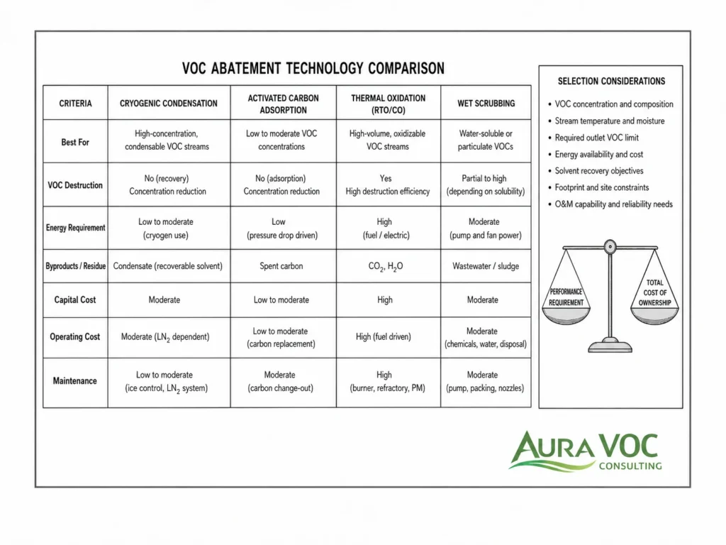
Cryogenic condensation is usually stronger for high solvent loading and bulk recovery. Activated carbon is often better suited for lower residual concentrations or polishing after condensation.
Carbon selection must consider saturation rate, bed temperature rise, humidity, regeneration method, changeout frequency, and fire risk for high-load streams. Where carbon would saturate quickly, condensation can reduce the inlet load and extend carbon bed life.
Cryogenic condensation versus thermal oxidation
Thermal oxidation destroys VOCs rather than recovering them. It can be effective for many continuous streams but may require significant fuel input when VOC concentration is low or variable.
For solvent-rich streams, oxidation removes the possibility of recovery. For halogenated or sulfur-containing compounds, combustion products may require downstream acid gas treatment and corrosion-resistant design. Cryogenic condensation is more relevant when solvent recovery, load reduction, or avoidance of combustion by-products is important.
Cryogenic condensation versus catalytic oxidation
Catalytic oxidation operates at lower temperature than thermal oxidation, but catalyst compatibility becomes a controlling issue. Silicones, phosphorus compounds, sulfur compounds, heavy metals, halogenated solvents, or particulate contamination can reduce catalyst life.
Cryogenic condensation avoids catalyst poisoning concerns but introduces low-temperature operation, nitrogen demand, condensate handling, and freezing risks. The better option depends on stream chemistry and operating profile.
Cryogenic condensation versus wet scrubbing
Wet scrubbing is only effective for VOCs that are soluble or reactive in the selected scrubbing liquid. Many organic solvents have limited water solubility or require chemical scrubbing systems that generate a liquid waste stream.
Cryogenic condensation is generally more appropriate for recoverable solvent vapors, while scrubbing is more relevant for specific acid gases, soluble compounds, or reactive contaminants. In some systems, scrubbing may be used with condensation where the stream contains both VOCs and inorganic components.
When a hybrid system is more practical than a single technology
A hybrid system is often practical when one technology handles the bulk load and another handles residual concentration. Cryogenic condensation can reduce solvent mass before activated carbon, oxidation, or scrubbing.
This approach can lower carbon consumption, reduce oxidizer load, stabilize downstream treatment, or improve solvent recovery. The tradeoff is additional equipment, controls, pressure drop, and maintenance responsibility.
Data Required Before Evaluating a Cryogenic Condensation System
VOC composition and solvent list
The solvent list should include all expected compounds, not only the main solvent. Minor components can control outlet concentration, freezing behavior, corrosion risk, or condensate classification.
Compound-specific data is required because each solvent has different volatility, freezing behavior, and recovery potential.
Flowrate range and operating pressure
Minimum, normal, and peak flowrates are required. Operating pressure matters where the condenser connects to vacuum systems, vessel vents, or headers with limited allowable backpressure.
Flowrate should distinguish between actual process vent flow and dilution air. Treating a diluted header as the design basis can lead to an oversized and costly cryogenic system.
VOC concentration and mass loading profile
The profile should include average load, peak load, peak duration, batch frequency, and operating steps associated with emissions. A single ppm value is not enough for design.
Mass loading is particularly important for batch processes because short emission events can set the required exchanger duty and nitrogen valve capacity.
Inlet temperature and humidity
Temperature affects sensible cooling load. Humidity affects ice formation, defrost frequency, and wastewater or defrost liquid handling.
If humidity data is missing, the plant may underestimate pressure drop risk, drain freezing, and maintenance frequency.
Batch schedule and emission peaks
The operating schedule determines whether the system runs continuously, cycles between batches, remains cold in standby, or shuts down between campaigns.
Batch timing also affects nitrogen consumption. A system held cold for long idle periods may use significant utility even when no VOC emission is being treated.
Required outlet concentration or emission limit
The outlet requirement determines the final temperature and whether polishing is needed. It should be defined by compound, averaging period, and measurement basis where applicable. For chemical-sector installations in Europe, BAT and permit requirements may also need to be checked against the applicable waste gas treatment reference documents.
A total VOC target, compound-specific limit, and mass emission rate can lead to different design decisions.
Existing fan, ductwork, and pressure drop constraints
Available fan margin, duct pressure limits, and upstream equipment sensitivity should be reviewed before adding exchanger and demister pressure drop.
For vacuum systems, pressure drop can affect pump performance. For vessel vents, it may affect pressure control or relief routing philosophy.
Nitrogen availability and utility constraints
Liquid nitrogen storage, delivery frequency, vaporizer capacity, pressure control, and low-supply response must be aligned with production requirements.
Utility constraints should be reviewed during peak production campaigns, not only normal daily operation.
Condensate reuse, recovery, or disposal requirements
The condensate route affects tank design, hazardous area classification, waste cost, solvent recovery value, and operating procedures.
The design should define whether condensate will be reused, sent to solvent recovery, segregated by campaign, or disposed of as hazardous waste.
| Required data | Why it matters | Common data gap | Consequence of missing data |
|---|---|---|---|
| VOC composition | Determines condensation temperature and residual outlet profile | Only total VOC is available | Wrong temperature setpoint or missed compound-specific limit |
| Peak mass loading | Sizes exchanger, nitrogen flow, and separator | Only annual or average emissions are available | Breakthrough during batch peaks |
| Flowrate range | Defines cooling load and pressure drop | Dilution air not separated from process vent | Oversized utility demand or poor feasibility result |
| Humidity | Determines ice risk and defrost needs | No water vapor measurement | Unexpected pressure drop and drain freezing |
| Outlet limit | Defines whether polishing is required | Limit stated only as “low VOC” | Overdesign or underdesign |
| Condensate route | Defines recovery value and waste handling | Reuse assumed without quality data | Unexpected hazardous waste stream |
FAQ: Cryogenic Condensation for VOC Abatement
What VOC concentration is needed for cryogenic condensation to be practical?
There is no universal concentration threshold. The practical fit depends on VOC partial pressure, gas flowrate, solvent value, outlet limit, inlet temperature, humidity, and nitrogen cost. A concentrated low-flow process vent is usually more favorable than a high-flow dilute exhaust.
Is cryogenic condensation suitable for low-concentration VOC emissions?
Usually not as the primary treatment method for large dilute streams. The system would cool a large volume of carrier gas to recover a small amount of solvent. In some cases, source segregation or upstream concentration can change the feasibility.
Does cryogenic condensation destroy VOCs?
No. It converts VOC vapor into a liquid condensate. The recovered liquid must be reused, recovered, stored, or disposed of through an appropriate route.
Can cryogenic condensation handle mixed-solvent VOC streams?
Yes, but mixed-solvent streams require compound-specific review. Heavier solvents may condense readily, while lighter compounds remain in the outlet gas. Campaign changes can also affect freezing behavior and condensate quality.
How does water vapor affect cryogenic condensation?
Water vapor can freeze in the exchanger, increase pressure drop, reduce heat transfer, block drains, and create defrost liquid. Humid streams may require staged cooling, upstream drying, heat tracing, or planned defrost cycles.
Why does pressure drop increase in a cryogenic VOC condenser?
Common causes include water ice, solvent crystallization, particulate fouling, aerosol deposition, demister loading, or condensate flooding. Differential pressure trends should be compared with humidity, outlet temperature, drain operation, and batch timing.
Why is liquid nitrogen consumption higher than expected?
Typical causes include higher inlet temperature, excess dilution air, high humidity, colder-than-required setpoints, poor heat recovery, standby operation, control valve hunting, or solvent loading above the design case.
A credible estimate should include carrier gas sensible cooling, VOC latent heat, water vapor condensation or freezing, heat losses, inlet temperature, heat recovery, standby operation, and the required outlet temperature. Using only solvent mass can significantly underestimate demand.
Can recovered solvent be reused in production?
Only if the condensate meets process quality requirements. Water, mixed solvents, impurities, reaction by-products, or campaign cross-contamination may prevent direct reuse.
Where direct reuse is not acceptable, the condensate may still be suitable for solvent recovery or controlled waste handling.
When is activated carbon still needed after cryogenic condensation?
Activated carbon may be needed when residual VOC concentration after condensation remains above the outlet target. Condensation can reduce bulk solvent load and allow the carbon bed to operate as a polishing step.
The carbon bed should be sized based on expected condenser outlet composition, temperature, humidity, and mist carryover risk, not only the untreated inlet stream.
Is cryogenic condensation suitable for pharmaceutical batch emissions?
It can be suitable where solvent emissions are concentrated, flowrates are manageable, and peak batch releases are well characterized. The evaluation should include campaign changes, solvent segregation, condensate quality, cleaning operations, and peak release events during drying, transfer, or vacuum breaking.
What data is needed before sizing a cryogenic VOC condenser?
At minimum: VOC composition, flowrate range, VOC concentration profile, peak mass loading, inlet temperature, humidity, outlet limit, operating schedule, nitrogen availability, pressure drop allowance, and condensate handling route.
The sizing basis should also define whether the system will operate continuously, cycle between batches, remain cold in standby, or integrate with a downstream polishing system.
Cryogenic condensation is most useful when applied to defined VOC sources with sufficient solvent loading, manageable gas flowrate, and a realistic condensate route. It is less effective as a general solution for large dilute exhausts, especially where humidity, pressure drop, or very low outlet limits dominate the design.
A credible evaluation must go beyond theoretical removal efficiency. The main engineering checks are solvent composition, peak mass loading, inlet temperature, water vapor, nitrogen demand, exchanger pressure drop, freezing risk, control response, and recovered liquid handling. These factors determine whether the system will operate reliably during real production, not only under nominal design conditions.
For many industrial plants, cryogenic condensation is best considered as a targeted recovery or load-reduction technology. It may operate alone in favorable cases, but it often needs to be integrated with polishing, solvent recovery, process safety controls, and maintenance procedures. The correct decision depends on how the vent behaves during actual operation.
For a technical assessment of cryogenic condensation suitability, prepare the VOC composition, flowrate range, concentration profile, peak mass loading, inlet temperature, humidity, operating schedule, required outlet concentration, nitrogen availability, pressure drop constraints, and condensate handling route.
AuraVOC can review the stream data, operating profile, and site constraints to identify whether cryogenic condensation is technically justified, whether polishing is required, and which design risks should be resolved before equipment specification.